As there are two sides of the coil in the magnetic field and indeed breaking field lines then the formula can be adjusted from E=Blv to take into account the length is twice as long. Also the coil can have any number of turns. This means that another modification can be made to take into account the fact that the number of turns is a multiplier of length. Therefore for an AC generator with number of turns (N) the formula for induced emf is
E=2BlvN
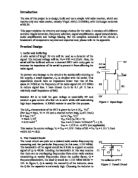
From the design brief it was stated that the generator turned at 2Hz must power a 1W bulb. From the Griffin Electrical accessories catalogue the following bulbs with relevant data and costs are available
The calculation for power was carried out using the formula
P=IV
Where P is the power, I is the current and V is the voltage. The current and voltage were both specified so the power could be directly calculated. Power is a measure of the rate of energy transfer from a component. For example a 60W light bulb similar to those found in the home would transfer 60J of power every second. This may not all be as light.
“About 90 percent of the electricity used by incandescent bulbs is lost as heat.”
So normal energy efficiency is around 10%, as useful light energy.
As can be seen from the calculations there are no bulbs that produce exactly 1W of power however there is an extremely close value of 1.05W for bulb 5 and a reasonably close value of 0.53W for bulb 4.
The voltage can however be altered by merely altering our design and using an ideal voltage to produce 1W of power. To do this the resistance of the bulb when running at its usual power needs to be calculated. The simplest formula is
R=V/I
Where R is the resistance, V is the voltage and I is the current. Resistance is a measure of the ratio of voltage to current across a component. Every component exerts resistance even the wires and this fact must be taken into consideration later on when calculating the number of turns required. Resistance is measured in ohms and ohms is given the Greek symbol omega Ω.
After calculating resistance the two formulas above can be combined to find the ideal voltage for the task. As current varies with voltage current should be eliminated from the equation for ideal voltage.
Rearranging R=V/I
R=V/I
RI=V
I=V/R
Substituting into P=IV
P=IV
P= (V/R) V
P=V2/R
Rearranging to find V
P=V2/R
PR=V2
V=√ (PR)
As the necessary P=1W
V=√R
What also can be calculated is the cost of each bulb. Bulbs come in packs of 10 so the cost for a pack divided by 10 is the cost for one bulb.
For our calculations we must assume that the resistance is constant with a change in voltage and current. In reality the resistance will increase with voltage due to lattice vibrations from the extra energy dissipated and thus the extra heat. As the lattice vibrates more vigorously the coulombs must follow a much more complex path and so the amount of time a coulomb takes to flow is less than usual, therefore the current decreases. Using the formula R=V/I as I tends towards 0 R tends towards infinity so the resistance increases with voltage.
In a cooler wire the lattice vibrations are low so the coulombs can pass through easier.
In a warmer wire the lattice vibrations are high so the coulombs find it harder to pass through.
In the design brief it was stated that the generator will be turned at 2Hz. To calculate the circular speed the formula below must be used
v=d/t
where v is the circular speed, d is the total circular distance and t is the time for one complete turn. d is basically the circumference of the motors circle it traces. This is in other words the length of the motor which is user defined multiplied by pi. So the formula for d is
d=πl
where l is the motor width and d is the total distance moved by the coil in one complete turn.
As we are working for one complete turn the time taken for one complete turn is the time period T. T is also calculated by the formula
T=1/f
Where T is the time period which is the time for one complete turn and f is the frequency which is the amount of complete turns in one second.
Therefore equating the equations the formula for circular speed is
v=πl/ (1/f)
v=fπl
Using the stated value of frequency 2Hz the formula usable for speed is
v=2πl
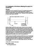
One final thing to take into account is the need to keep the generator width below 20cm or moreover the generator’s diagonal width less than 20cm. The coil will be arranged in a square on the end of the generator on either side as shown below
The width of the coil can be found by the diameter of the wire as given in the griffin electrical accessories catalogue. The wire to be used is enamel coated copper. Copper is an extremely good widely available cheap wire so is good to use. The enamel coated wire is also the best as if it was bare there would be no more than one single coil due to short circuits. If plastic coated copper is used the coil width is going to be much much to big.
So now we can deduce that using bulbs 4 and 5 the following turns of wire are necessary to produce a power of 1W. Below are the results for bulbs four and five for a core width of 17cm
As can be seen the combination of wires 7, 8 and 9 and bulb 4 and wires 6, 7, 8 and 9 and bulb 5 work.
However when we take into consideration that the length of the wires in some cases is a great as 18089m then the resistance from the wires is going to be so great that it must be regarded.
Internal resistance can play major factor in the designing of the circuit and generator. Internal resistance is the resistance generated inside a power supply such as a battery or generator. It is often denoted by r as opposed to R. it is depicted in circuit diagrams with a small resistor inside the power supply.
r
R
The resistance of the wire can be worked out using the resistivity and information already gained.
The formula for resistance involving resistivity is
r=ρl
A
Where r is internal resistance, ρ (rho) is resistivity, l is the total length of the wire and A is the cross sectional area of the wire.
ρ for copper wire is 1.72x10⁻⁸Ωm and therefore is merely a constant as it is a property of the material. L can be changed to be specific for an AC generator. The total length involves the length of each side multiplied by the number of coils on each side multiplied by the number of sides in other words l=4lN. A can be found from the griffin electrical accessories catalogue.
So equating the equation for r
r = ρ4lN
A
Internal resistance removes some of the total voltage to be dissipated in the external circuit. The emf is therefore the sum of the combined voltages. As voltage is the product of resistance, whether it be internal or external, and current. The equation for the total emf including the internal resistance is
E=IR + Ir
Where E is the emf, I is the current, R is the external resistance and r is the internal resistance.
IR is equal to the voltage across the bulb and therefore can be replaced by the voltage previously calculated to give 1W of power to the bulb.
E is also equal to another formula 2BlvN so equating all 3 formulas gives an expression with only 1 variable N
2BlvN = Videal + ρ4lN
A
Rearranging the formula to get N as the subject the formula becomes
2BlvNA = AVideal + ρ4lN
2BlvNA – ρ4lN = AVideal
N (2BlvA – ρ4l) = AVideal
N = AVideal _
(2BlvA – ρ4l)
All the values are now either constants or things that can be worked out.
Below are the results of finding the generator width’s using a core of 17cm
The cells with error written are such because of an incompatibility with the bulb and the wire. Also the wire/bulb combinations with diagonal lengths greater than 20 cannot work either.
As is shown above there are 6 viable options for the generator combination. Bulb 4 with wires 3, 4, 5 and 6 and bulb 5 with wires 3 and 4. However some combinations use less but the wire is more expensive whereas some combinations use more wire but it is cheaper. The only true way to choose defiantly a wire and bulb combination is to work out the total cost for each generator combination.
The prices are given in the griffin electrical accessories catalogue and are shown below with the price per meter found.
No using the viable generator combinations the cost can be calculated. As the product to be designed is a prototype the costs are likely to be high as commercial materials are likely to be much cheaper than the materials from the griffin catalogue.
The cheapest option is bulb number 4 with wire number 4 at £27.20. However the best bulb to use would be bulb 5 and the cheapest with that bulb is wire 3 at £35.80. Only testing would reveal the best bulb and wire combination from the viable options. Bulb 4 may have problems working at higher than normal voltages so would be unviable but bulb 4 is also a cheaper option that bulb 5 which is a good reason to choose the bulb in a product for marketing.
Testing
During the design many things were assumed. The strength of the magnet was given to be around 50mT but this was approximate. The resistivity of the copper wire was assumed to be 1.72x10⁻⁸Ωm but this value can vary for different types of copper wire. The resistance of the bulb was calculated from the given values of voltage and current, for bulbs 4 and 5 this was 23.33Ω and 11.67Ω respectively. However the resistance will very likely change with voltage due to increased lattice vibrations.
Also the final construction needs to be tested to see if it works the method for the final construction will use the calculated values.
The magnetic field strength in the design brief was not given to be exact. A simple experiment to determine the magnetic field strength is the current balance. This device uses the principle of Flemings left hand rule where a wire with a current placed in a magnetic field feels a force so long as the wire and the magnetic field are perpendicular in some component.
In the current balance a wire is passed through a magnetic field and joined round to form a circuit at its pivots with a power supply. As a current is passed through the wire between the magnetic field the wire feels a force. Before the current is switched on the balance is balanced. Once the current is switched on the balance is rebalanced using small masses and the change in force can be calculated from the change in mass. Then the current can be measured from the ammeter and the magnetic field calculated.
Method
Take a current balance and connect it as shown in the diagram above using the supplied horseshoe magnet and make sure the balance is calibrated. Place a 0.25g mass on the balance and switch on the power supply. Adjust the current on the power supply until the balance is balanced. Record the current and input into the spreadsheet below.
Repeat the experiment using masses of 0.5, 0.75, 1.0, 1.25, 1.50, 1.75, 2.0, 2.25 and 2.50g
Then work back down the masses taking 0.25g off each time to gain 2 readings for each mass.
Input both sets of readings into the spreadsheet below and plot the force against Current. Then find the gradient this gradient is the inverse of magnetic field strength multiplied by the length of wire in the horseshoe magnet. So the magnetic field strength is
B= 1
ml
Where B is the magnetic field strength, m is the gradient where m=Δy/Δx, and l is the length of wire in the magnetic field. For example if our readings were those shown below then and the length of wire in the magnetic field was 10cm then;
Using these values a graph can be drawn with error bars which can then be used to draw a line of best fit. The gradient of this line can be found and used to calculate B
m=Δy
Δx
m= 4.880-0
2.450E-02-0
m=199.18
so using B=1/ml
B= 1
Ml
B= (1.99.18x0.1)-1
B= 0.05021T
B= 50.21mT
So the magnetic field strength would more precisely be 50.21mT rather than approximately 50mT.
There are no major safety considerations apart from normal precautions when using electric power supplies, do not use with wet hands and always start from a low current and turn the supply up rather than start from a high current and turn it down. Also when the current is being switched on keep hands clear of the balance as if the current is to high fingers could become trapped under the calibrating mass.
A simple test can be carried out to determine the exact resistivity of the enamel coated copper wire.
Using the specification catalogue find the wires diameter. Take a meter ruler and tape the wire down the length of it. Using a crocodile clip attach one length of wire connected to an ammeter to a power supply and clip the crocodile clip onto the wire at 10cm. Attach another wire to a jockey and connect this wire to the power supply also. Connect a voltmeter's terminals to the crocodile clip and the jockey as shown below.
Using the Jockey connect lengths of 0.05, 0.1, 0.15, 0.2, 0.25, 0.3, 0.35, 0.4, 0.45 and 0.5m to the circuit. Record the voltage and current in the spreadsheet and use the values to plot a graph of resistance against length.
Using this graphs gradient will give R/l which can then be put in the formula ρ=RA/l or ρ=mA
For example if we had wire 4 diameter 0.56mm and a voltage of 1mV all the time then the currents would be around those shown in the spreadsheet.
The point at 0.05m shows that by drawing a graph it eliminates anomalous results.
Therefore calculating the gradient
m=Δy/Δx
m=0.0345-0
0.5 – 0
m=0.0345/0.5
m=0.69
Therefore using the formula ρ=m-1A resistivity is
ρ=m-1A
ρ=0.69-1x2.46x10-7
ρ=3.57x10⁻⁷Ωm
This value of resistivity can then be used in calculating the number of turns of wire.
So in this case the resistivity would be slightly more this is merely due to impurities and the like affecting the resistivity property of the material.
It is likely as explained earlier that the bulb’s resistance will go up as the voltage increases. A simple experiment can be used to determine the bulbs resistance at these new voltages and the design can be modified accordingly
Set up the circuit below 2 times using different equipment and different bulbs of the same specification.
Using voltages of 0.5V, 1.0V, 1.5V, 2.0V, 2.5V, 3.0V, 3.5V, 4.0V, 4.5V and 5.0V set the circuit up and record the current and voltage and plot a graph of current against voltage. The gradient of a V-I graph if V is on the X axis and I is on the Y axis is R-1 therefore to find the resistance for the bulb a tangent should be drawn at the point for which the resistance is needed (in the case of the example at the ideal voltage of bulb 4). The resistance can then be calculated by finding the gradient of the tangent and using R=m-1 as shown below.
From the graph at the point where V=4.83V (the ideal voltage for bulb 4) the gradient of the tangent is
m=Δy/Δx
m= 0.3-0
0-6.00
m=0.3/-6.00
m=-0.05
therefore the resistance is equal to m-1 so
R = m-1
R=-0.05-1
R=20Ω
The negative sign can be neglected as resistance is a scalar quantity so the modulus of the m-1 can be taken to find the true R or in other words the negative can be ignored.
All of these values can now be put in the main spreadsheet and a new value for the number of turns, the diagonal width and the cost can be calculated and the design refined.
To test whether the final circuit works is slightly more difficult than merely attaching a voltmeter and ammeter as the generator is AC and these only work in DC. Firstly the generator must be spun at 2Hz. Although in the real world this would not be done, for testing a motor will be used to spin the generator at 2Hz. This can be measured on a cathode ray oscilloscope which displays a voltage time graph set up like below.
The time base can be set which basically means how many milliseconds per centimetre on the display and the voltage can be set which is just how many volts per centimetre on the display. As the motor should be turned at 2Hz and the cathode ray oscilloscope (CRO) has a display of 10cm wide the time base should ideally be set at 50mscm-1 this would mean that the entire display would cover a time of 0.5 seconds. As the frequency is 2Hz then this equates to the time period so the display would show one oscillation. From the spreadsheet the ideal voltage is 3.42 volts for the best bulb, bulb 5. therefore a good range would be 4V. As the oscilloscope measures voltage with time the entire display must show up to 3.42V and down to -3.42V or for the range selected +4V. This means a suitable division would be 4V per 5 centimetres or 0.8Vcm-1. The oscilloscope should look something like
(Not to scale)
The voltage can then be measured of the oscilloscope by reading of the peak voltage. The voltage decays like this due to the component of motion perpendicular to the magnetic field. As the generator turns the velocity changes with time. When the generator is horizontal all of the velocity is of vertical component whereas as the generator continues to turn the component of velocity is split with more of the velocity in the horizontal direction, parallel to the magnetic field and less of it in the vertical direction, perpendicular to the field. As the generator becomes vertical there is no perpendicular component of velocity so no emf is induced so we get a sinusoidal wave like that shown above. As the generator rotates 180 degrees there is a total reversal in the way the current flows due to the reversal of the poles of the sides of the generator. The poles start reversing when the generator is vertical hence there is no charge as the going from positive to zero to negative or vice versa. Then as the generator rotates the send 180 degrees the poles reverse again with no charge and hence no current when the generator is vertical in the magnetic field
The peak voltage measured should be the voltage necessary to produce 1W of power in the bulb. So in 1 complete turn the voltage peaks when the generator is horizontal decreases to zero at the vertical then increases in the opposite direction to the opposite horizontal.
Again there are no major safety issues except the generator is spinning and fingers maybe trapped, also as with all of the other experiments simple precautions to do with electricity must be observed such as don’t touch bare live wires, don’t hand wires with wet hands and always switch off the power at the mains before leaving dismantling or modifying the circuit in anyway.