My chosen variable in this experiment is going to be to see how altering the length of the wire affects the resistance.
As I am going to need to use several different lengths of wire in this experiment, it would be more economical to use something called a sliding contact. This is where a long length of wire, that is to be tested for resistance, is placed in the circuit, held in place at either end by two crocodile clips. To test the resistance of the different lengths of wire, the crocodile clips are placed along the wire, so that the desired length is between the clips. The wire in between the clips will be live when a current is passed through it, but any other wire that is outside of these clips will be neutral. The reason for this is because electricity is lazy, and it will take the quickest and easiest route.
The lengths that I have chosen to test are 200mm, 400mm, 600mm and 1000mm. The reason I have chosen this particular lengths is because they are ion a logical sequence and are well spaced out and easily measurable. This will hopefully give me good averages, and a good graph.
Dependent variable
This is what I am going to be measuring. This shall be the resistance of the wire. I shall do this by using an ammeter and a voltmeter in the circuit. I have chosen to do this because it is more accurate than using a separate resistance meter. I have decided to rely on these instruments, because I know that the power-packs indication of voltage is highly inaccurate. I shall test each length of wire three times, to make sure that I get a good average. The way I shall calculate the resistance shall be using the following formulae:
Resistance I = potential difference (p.d) across resistor in volts (v)
__________________________________________
Current flowing through it in amps (I)
Fair Test
To make sure that this experiment is conducted as fairly as possible I have come up with a number of things that need to be kept constant. The reason I need to keep conditions on the experiment as regular as possible is so that I can get accurate results and graph, otherwise there is little point of conducting the experiment.
The voltage, all the apparatus and measuring equipment, the wire that is being measured for resistance, and accurately measuring the lengths to be tested all must be kept the same.
I shall keep the length the same by using the same meter rule every time I measure the length of wire that is to be tested, and making sure that the measurements are exact.
For each individual experiment I am going to make sure that the voltage is the same, by checking the voltmeter and adjusting the dial accordingly, because the voltage is known to fluctuate as the experiments go on.
Resistance is affected by heat, and one of the products of resistance is heat. So I will make sure that I let the apparatus cool down for about a minute in between each individual experiment. The heat causes the atoms in the wire to vibrate quicker causing higher resistance.
Safety
In this experiment we are using a bare electric wire, which could e very dangerous if the voltage is not kept low. As we are using electricity we must be ever vigilant of the dangers that it can cause, especially looking out for water, which might be on the lab benches from previous experiments that day.
All of the usual lab rules to this experiment, as they would do with any other. Such as no running etc.
Equipment
- 1 x power pack
- 6 x power leads
- 1 x ammeter
- 1 x voltmeter
- 1 x un-insulated wire
- 2 x crocodile clips
- 1 x meter rule
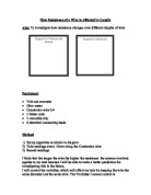
Diagram
How to put the apparatus together
-
Connect the power pack to the mains and switch it on at the plug socket. However make sure that the power pack is turned of at the power switch.
- Take 2 wires and connect them to the negative and positive terminals of the A.C supply.
- To one of the wires connect one side of the ammeter.
- Take another wire and connect it to the other side of the ammeter.
- Assemble the voltmeter component, with a wire either side of the voltmeter.
- Your apparatus should now look like this:
- Connect your voltmeter the rest of the apparatus in the way shown below:
- Attach the crocodile clips to the end of the wires still left bare.
- Your completed apparatus should now look like this:
Preliminary method
- I have decided to keep the voltage to 2 volts. This is because it is a fairly low voltage and is quite safe, bearing in mind there are bare wires in this experiment. Also I have chosen this low voltage because it means from the findings of my preliminary tests I can raise or lower the voltage if need be.
- The apparatus will be set up as described I the diagram. And the wire will be placed in the crocodile clips.
- 20cm of the wire will be in the clips.
- I will repeat each test for resistance on each length 3 times to make sure that I get a good average.
- I will allow the wire to cool down for at least 30 seconds in between each test.
- I am going to draw up a results table so that I can record my findings accurately.
Results Table
As my graph to the preliminary testing shows, everything seems to have gone according to plan, and there were no anomalous results.
This proves that my methods and predictions are accurate and correct.
I have conducted these preliminary tests in exactly the same way I had planned to conduct my main experiment. The purpose for these preliminary tests was to see if there was anyway in which I could improve my method, and to see what I would have to change to the experiment to make it work for me as best as possible. However, I came across no problems and there was nothing, which I could see that needed changing. Therefore I am going to adopt my preliminary tests as my main experiment, because if I repeat the experiment, I will get exactly the same results.
Analysis of graph
From my graph I have proved my prediction that resistance is proportional to length because of the line of best fit that I have got on the graph.
Conclusion
In my prediction I said that resistance is directly proportional to length, and I have proven this to be correct, by following by plan and a well worked out method that is both fair and accurate. The length of the wire affects the resistance of the wire because the number of atoms in the wire increases or decreases as the length of the wire increases or decreases in proportion. The resistance of a wire depends on the number of collisions the electrons have with the atoms of the material, so if there is a larger number of atoms there will be a larger number of collisions, which will increase the resistance of the wire. If a length of a wire contains a certain number of atoms when that length is increased the number of atoms will also increase. From my results table and graph I can see that my results that I collected are very reliable. I know this because my results table does not show any individual anomalous results this means that I did not have to leave any results out of my averages because they were anomalous. Also on the graph I can see that none of the averages plotted are anomalous because all the averages lie along the same straight line.
Evaluation
If I were to make any changes to my experiment I would have put the voltmeter apparatus on the wire that was being tested. By using this way it would of measured the voltage of that wire, instead of the wore that was being tested and the rest of the circuit.
Also I would of tested the same wire, as I had done in the experiment described above, but used different thickness of the wire, to see how this affected the resistance to add to my investigation.