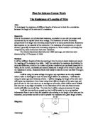
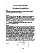
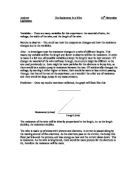
Diagram:
Accuracy:
I will use a 2 volt power supply from a mains powered power pack. I am using this opposed to batteries because the batteries available to me are not fully charged and may run down during my experiment giving an unreliable power source and unreliable results.. I can achieve more accurate and useful results if I can keep the number of variables down to one. This way my analysis of my results will be clearer. For this same reason I will use only one thickness and kind of wire.
I will check that the ammeter and voltmeter that I use have their needles on zero before I integrate them into my circuit and I shall double check my circuit set up prior to starting my experiment.
I will first test my circuit with no test wire, and just touch the crocodile clips together so that I can subtract the resistance of the circuit’s wire.
Fair Test:
I will try to follow Ohm’s Law: the resistance of a metal wire or a piece of carbon will stay the same as conditions are not changed e.g. temperature.
I will use the same voltage, wire width and size and I will repeat experiments to find an average in case one piece of wire has impurities in it. I will use the same volt meter and ammeter and the same wires to connect the components as some may have more resistance than others. I will conduct my experiment within one hour so that day to day climatic changes will not affect my results as temperature can affect the resistance of a conductor. I know this to be the case because I have experimented previously with thermisters.
When a substance increases in temperature, it’s atoms vibrate more. This means that the free electrons which are free to move throughout the crystalline structure of a metal are more likely to hit a fixed vibrating atom, thus slowing it down and reducing the current of the electricity.
I shall be using a low voltage so that the wire does not get too hot. This heat energy in transferred from the kinetic energy of the free electrons when they collide with atoms in the metal. The kinetic energy is dissipated through the metal in vibrations which generate heat due to friction. This should reduce any feedback resistance generated by heat of the wire generated by the resistance created by the wire itself.
I have found from prior research and experimentation that if I were testing different widths of wire, the thinner ones would have more resistance. If I were experimenting with types of metal, gold silver and copper in that order would have the least resistance.
Safety:
All the connecting wires will be insulated to prevent shocks or short circuits. I will be using a low voltage so that the test wire does not get too hot and to lessen the possibility of damage from an electric shock.
I will not touch any electrical equipment with wet hands and I understand what to do in the event of someone receiving an electric shock. There is also a carbon dioxide fire extinguisher in the laboratory in case of an electrical fire.
Equipment:
Power pack, red and black insulated wires, two crocodile clips, volt meter, ammeter and 3 lengths of constantan 24 swg wire,
Prediction:
I predict that the resistance of metal will be low because it is a conductor, and the metal that I am testing is used in electrical wiring so I expect to have a low resistance in comparison to most other metals not used in wiring otherwise it would not logically be used as such.
I predict that the resistance will increase in direct proportion to the length of wire. I base my prediction on the scientific theory that I have read up on. The above will occur because:
The amount of resistance that a wire has is determined by the metal, it’s temperature, its length and the width of it. Electric current is caused by the movement of electrons. Metals are made of tiny crystals within which atoms are arranged in a regular pattern but the electrons do not stick with any one atom. This is what makes metals such good conductors. The electrons fill the space around the atoms and when they move there is an electric current.
The variable which I will change in my experiment is the length of the wire. A longer wire will contain more fixed particles made of protons and neutrons for the free moving electrons to collide with. As these free electrons move they bump into these and it is these collisions which create resistance. So a longer length of wire will have greater resistance than a shorter one.
Results Table:
Results
First results:
2nd repetition:
3rd repetition
Observations:
The circuit became warm when a current passed through it and increased in temperature as the resistance increased.
The resistance of the circuit alone, not including the test wire was 0.9 Ohms.
Conclusion:
My prediction was correct. The resistance went up as the length of wire increased at an average 0.2 Ohms per 10cm, that is approximately 0.02 Ohms per cm, and roughly 0.002 Ohms a mm.
In general if you double the length then you get very roughly twice the resistance.
As expected the current decreased with increased wire length.
Evaluation:
I have found several faults with my experiment. The first is that resistance creates heat, (and light too if enough voltage is used) and increased heat in a conductor also increases the resistance. This will therefore exaggerate results as the wire gets longer, because a longer wire has more resistance, so it will create more heat, and therefore more resistance, and therefore more heat, and so on. This is made worse by the heat conductive nature of metals due to their free electrons.
The theory behind this that when a substance increases in temperature, it’s atoms vibrate more. This means that the free electrons are more likely to hit a vibrating particle.
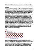
This should provide me with a graph with curve with an increasing gradient similar to the one below:
Which is not what mine resembles, mine seems to increase in steps:
Another problem concerns how I set up my circuit. Looking back I should have set it up as below.
For my experiment I placed the voltmeter in the wrong place. I wanted to pass exactly two volts through my piece of test wire. Instead I was measuring the voltage of the whole circuit which would have included the power consumption of the ammeter, though seeing as this would have been a constant, it should not have effected my results over all.
Without the opportunity to re-take my results or measure the overall effect of measuring the potential difference of the whole circuit instead of just that across my wire I have to use what results I have. Unfortunately no one else in the class carried out the same experiment as myself, so I am unable to compare my results.
I think that due to the unprecise nature or needle based meters and the problem of the heat and resistance problem it would be very difficult, if not impossible to find any precise formulas for calculating resistance from wire length.
If I were to repeat this experiment I would like to use precise, digital ,electronic volt and ammeters. I would also like to measure the temperature of the wire, and keep it at a constant temperature by refrigeration.
I would also correct my placement of the voltmeter. I would like to expand my experiment to look the other variables, change the voltage, type and width of wire.
Bibliography:
Microsoft Encarta 95 CD ROM
The On-line Britanica Encyclopaedia
Co-ordinated Science 2 Edited by Ken Dobson & Chris Sunley
GCSE Double Science Physics The Revision guide (Higher Level) Edited by Richard Parsons