The Science
The equation I = V/R is known as Ohm’s Law. It means that the amount of current through a material is proportional to the voltage divided by the electrical resistance of the material. The relationship between these three factors was the true beginning of the analysis of electric circuits.
Preliminary
Before we start with the main experiment we have to do a preliminary experiment, to choose the main factors, which include:
- How to set up the wires and volt- and ammeter
- How to measure the lengths of the wires
- How much current to use
In our preliminary we decided to keep the current at 2 A because this would not change the temperature of the wires and therefore affect its resistance. We recorded only the data of each of the six wires over a distance of 1 meter. The results we got are shown below:
By looking at this preliminary we were able to make the first points about the trend. The main thing we noticed was that as the diameter of a wire increases, the resistance decreases. In other words, the thicker the wire, the lower its resistance and inversely.
Equipment and Setup
For this investigation we need the following Equipment:
- Ammeter
- Voltmeter
- Nichrome wires
- Electric Wire and crocodile clips
- 1 Meter Ruler
- Battery
We will set up my electric circuit with an electric battery and connecting the electric wires to it. We will then connect the Ammeter in series and the voltmeter parallel to the metal wire. The metal wire will be stacked on the ruler first. The crocodile clips will then be connected to this wire on one end and on the other end with different distances.
Method
For doing this investigation we will set up a simple electric circuit, to be able to read and notice the current and voltage of wires. To get a very accurate result we will measure the wire in a range from 10 cm to 100 cm in intervals of 10 cm each. To change the length of the wires we will use the crocodile clips, which we will move apart after each measurement, while the wire is attached to a 1-meter ruler for accurate results. As there will be an ammeter and a voltmeter we will be able to notice down both, the current and the voltage and afterwards calculate the resistance by dividing the voltage by the current.
We will be using six wires with different thicknesses, which will be 22, 24, 26, 28, 30, and 32 SWG. As each wire is labelled with this code, we do not have to calculate the diameter, because they are already measured.
It is very important in this investigation to try to keep an as constant temperature as possible, so it does not affect the resistance. If the temperatures of the wires increase rapidly, this could lead to illusions in our results and analysing, because too hot wires will increase the resistance.
In our preliminary experiment we noticed that the same wire with different currents caused the temperature of the wire to increase thus affecting the resistance. We found out that if the current increases, the wires get too hot very quickly. Therefore we decided to leave the current at 0.2 A for our main experiment, because we did not want the temperature change to occur as we are investigating the length of wires and not the temperature.
The circuit diagram below shows how we are going to set up our electric circuit.
Prediction
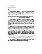
From own scientific knowledge and a bit of research I know that the resistance increases if the resistor (in this case the wire) is thinner, and when it is thick, the resistance is lower. This is because electrons have a negative charge and have to move past positively charged ions. As there will be an attraction between the charges and ions, the charges will stop or slow down flowing. This explains that the longer or thinner the wire is, the higher its resistance as there will be more ions on the way. A relatively short or thick wire will have very low resistance as the chance of ‘meeting’ an ion is lower. This can be explained as the longer the wire, the more collisions take place between electrons and ions. This is what causes resistance. The term “resistance” comes from the ions resisting the free moving electrons. The diagram below shows this clearer:
Furthermore I also predict that the length of the same wire will be directly proportional to its resistance. This means that if you double the length of the wire, the resistance also doubles. I think that double the length means also double the number of ions in the wire. Therefore the collisions between electrons and ions would also double, which finally means double the resistance.
Using Ohm’s Law we were able to calculate the resistance of each wire. These are the results:
To be able to compare the resistances of all the wires, I will now show all resistances of the different wires in one table:
By doing this investigation we found out that different thicknesses of wires and different lengths have also different resistances. The numbers, labelling each graph are its diameter, in order to compare its thickness to other wires. It is given in millimetres.
As you can see the wire with the wire with the diameter 0.27 mm has the highest resistance. The scatter graph above also shows that the thickest wire, which has a diameter of 0.71 mm, has the lowest resistance. By using these two examples we can see one trend in the diameter: The thicker a wire is, the less resistance it has.
I = current (Amps); V = voltage (Volts); R = resistance (Ohm, Ω)