Process
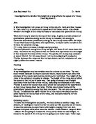
My first task was to familiarize myself with the task and how I was going to approach the problem. I had to come up with a way of fixing a stable runway that could withstand a weight of over 100g without giving way. I was presented with a piece of plastic runway that was to act as my ski slope. At first I just attached the one end of the runway, thinking that this would be enough to hold the ramp steady. It did, until I used the heavier balls and then the ramp was bending in the middle so it was going to give me anomalous results. It was a problem that I fixed with a roll of gaffer tape and I stuck the sides to the table. This couldn’t move.
I the attached a 100cm ruler to a clamp stand that was holding the elevated end of the ramp, so that I could measure the height of the ramp to an accuracy of 0.1cm.
Below is a picture of the chosen set up of my equipment for the experiment.
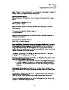
The ball bearings that chose were all of different masses and sizes, but all made from steel. This was to make the test as fair as possible. These are the bearings that I chose:
Ball No. Mass/grams Diam/mm
1 8.3
2 28.1 19.1
3 35.0 20.7
- 66.4
- 117.3 35.0
To measure the mass of the bearings by using a scale that measured up 200grms. To stop the balls from rolling off the scales I had to put them in a small bowl. I first put this bowl on the scales and then tared the scales so I could read the mass of bearings. To measure the diameters of the bearings I used vernier calipers and these are accurate to 0.1 of a mm so they were very accurate readings. I took three readings for each bearing for both measurements and then took an average of my results.
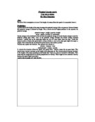
The bearings will land in a tray of sand that will be positioned on the floor below the table and at a distance of 1m from the table edge. This is shown below:
To try and keep the test fair I am going to use the same equipment every time I do the test. I may have a problem in that the balls will be being used at least three or four times in quick succession and they may have sand on the m when they come out of the pit. This sand would then be placed onto the runway and so when the next run was recorded the bearing would be experiencing more friction and my results would be wrong. To overcome this problem I intend to wipe the bearings with a dry cloth after each run and this will hopefully get rid of any sand that is on the bearings.
After ensuring a way of making the test a fair one I have also had to think about safety. In my experiment there are not any large worrying safety concerns, but as I am going to have quite heavy steel ball bearings flying off of tables, I am going to have to make sure that there is no-one in their flight path before I let them go, or someone will end up with an injury.
My next task was to decide exactly what I was going to test and how I was going to go about proving my results. I used the laws of projectiles to help explain this. Below are my calculations
h = The height of the top of the table from the tables surface
h = The height of the bearing from the floor at the moment of take-off.
so
Using h to find v
GPE at top of ramp =mg h
KE at bottom = ½ mv
The m’s cancel so I am left with
v = 2gh
Using h to find R
Vertical Motion
Using the formula s=ut +1/2 at u = 0
v = 2gh
a = gravity = g
t = t
s = h
s = ut + ½ at
therefore
h = 0 + ½ gt
So
t= 2h
g
Horizontal Motion
Speed = Distance or Velocity = Range
Time Time
So
Range = Horizontal Velocity x time of flight
= 2gh 2h/g
So
Range =2 h h
As I have said before, the ball bearings should all travel the same distance no matter what their mass. Below is the calculation of Range for the bearings
with h = 60.0cm and h = 88.4cm
Using the above formula I found that the true range of the ball bearings should be approx. 146cm rounded to the nearest cm.
As you can see, apart from the lightest bearing, they all seem to follow a pattern of increasing range against increasing mass. But I have shown theoretically that mass shouldn’t enter into the picture.
I tried the experiment again and this time h = 50cm. The expected range in this test was 133cm. My results are shown below:
As you can see, these followed the same pattern. Over the page you can see the graphs of these two sets of results. You can clearly see the ‘anomalous’ results that have been recorded for the bearing of 8.3g
I do believe however that I can explain this.
The ramp that I was using was of the shape shown below and only measured about 15mm across. This meant that when the larger bearings traveled down the ramp, they had two points of contact, one on either side of the ramp. This would increase the amount of friction that they would have acting on them. The smallest bearing didn’t have this problem however. It fitted nicely into the cusp and so had only one contact point and therefore had less friction to fight against. Below is a diagram to explain my idea further.
However none of my results are near to the range that I predicted. This may be down to human error but I think that it is very likely that some of the energy that is stored in the bearing at the top is not being transferred into Kinetic Energy due to the friction on the runway. The bearing will also encounter air resistance on it’s descent and this will slow it down even more. The bearing is not just sliding down the ramp, it is rolling. Some of the KE will be transferred into making the ball roll. The rotational motion will use up some energy. But because the smallest ball bearing was very small and light, it would not have as much friction on the runway or air resistance to contend with and so more PE would be transferred to KE at the point of take-off. The results appear to be relative to mass because, the mass dictates the size of the ball and so, how much friction and air resistance it encounters on the way down. However my results aren’t what expected I had not anticipated that the results would be so far off the mark. But in using just a simple version of the formula for PE=KE I made the assumption that there was no friction or air resistance at all and that the ball slid down the ramp without rolling.
I should have used the following formula:
GPE = KELinear + KERotational +Work Done Against Friction
or
mgh = 1/2mv + 1/2I + WD
If I had used this formula then I would have probably got some results that were a lot nearer to the predicted ranges as I would have been taking into account the other factors.
Extra Studies
If I were to do the experiment in more detail, I could change the angle of take-off. By raising the other end of the ramp and making h larger, some of the KE would be transferred back into PE and the take-off and range would be affected.
Because I cannot conclude there is a pattern from just one result, I would do the investigation again but with a larger ramp as this would make it a fair test and allow only the one contact point on all the bearings thus reducing the friction and maybe allowing them to travel further. The theory would certainly show that they should all get somewhere near to the calculated ranges.
Conclusion
Because I would not be able to get a friction free surface to perform my experiment in, I wouldn’t expect perfect results and at the beginning I didn’t expect to encounter the problems with the ramps width and the increased friction. Through the use of the formula I have shown that mass of the ball bearings had nothing to do with the range.