Results:
From the results gathered the decision was made to use nichrome wire for the final experiment. This is because it has a higher resistance than copper, so larger differences are apparent when the wire length is changed. The voltmeter and ammeter available for the experiment both only display to two decimal places, so the readings obtained if copper wire was to be used would be very inaccurate. Also, from the preliminary experiment the choice was made to use 0.5amps as the control current. This is because before the experiment 500mm of each wire were tested at 1 volt, the original control measurement. 1 volt proved to be too high a level of power; the copper wire got extremely hot and melted and the nichrome wire got too warm to handle safely. The heat is caused by the collisions between the free electrons and the atoms of the metal. The collisions give the atoms more energy, making them vibrate faster and thus increasing the temperature of the wire. This action becomes more pronounced the longer electricity flows through the wire, as the increased vibration means the electrons collide more often, further increasing the temperature and the vibrations, continuing in a vicious circle until the metal reaches its melting point and breaks.
Prediction:
From previous knowledge and the results of the preliminary experiment, I predict that as the length of the wire increases, the resistance will increase.
Variables:
Type of metal: This must be kept constant to ensure that resistance change is purely down to length change rather than the different molecular structure of other metals
Length: The length is the variable to be changed to see how it affects resistance. If length was kept constant then there would be nothing changing and the experiment would be pointless
Diameter: The diameter of the wire must be kept constant, as a thicker wire would have less resistance due to the increased space available for the electrons to flow and a thinner wire would have more resistance due to the decreased space available for the electrons to flow.
Temperature: Temperature is a variable that may affect resistance for the reasons illustrated in the preliminary experiment. Temperature should be kept constant, but due to practical issues this is impossible with the facilities available. Therefore this must be taken into consideration when analysing the results.
Amperage: The amperage is to be kept constant at 0.5 amps. This is because voltage can then be measured to determine how many volts are required to allow 0.5amps to flow, and resistance in that length of wire can then be calculated. If the amperage was changed halfway through the experiment then the results from that point onwards would be useless.
Equipment used: The equipment used must stay the same for all of the tests performed, as changing the equipment may give different readings due to slight differences in the new equipment. This is particularly important for the voltmeter and ammeter, as differences in these would definitely alter the results, making them inaccurate.
Equipment:
1 power pack: to supply the DC electricity needed to perform the experiment.
1 1000mm ruler: to accurately measure the length of wire used.
1 reel of 0.37mm diameter nichrome wire: the wire to be tested.
2 crocodile clips: to connect the nichrome wire to the circuit.
1 voltmeter: to measure the voltage across the nichrome wire during the experiment.
1 ammeter: to measure the current across the nichrome wire during the experiment.
4 lengths of school standard insulated electrical wire: to connect the circuit together.
1 pair of scissors: to cut the nichrome wire from the reel.
1 micrometer: to measure the diameter of the nichrome wire to make sure it stays constant.
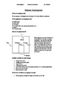
Equipment Diagram:
Method:
- The equipment was gathered and the circuit set up as shown in the equipment diagram
- 500mm of nichrome wire was measured and cut using the scissors.
- The wire’s diameter was checked with the micrometer to ensure that it was 0.37mm. A high quality reel of wire was selected for the experiment, to minimise changes in diameter.
- The power pack was set to 0 volts and the wire connected at 50mm using the crocodile clips.
- The power pack was turned on and the dial slowly turned until the ammeter reading was 0.5amps.
- The voltmeter reading was recorded, and the experiment repeated 3 times using the same length of nichrome wire.
- The crocodile clips were removed and placed at 100mm along the wire (measured with the ruler).
- The experiment was again repeated three times for this length and all readings recorded.
- The process was repeated increasing 50mm each time until 500mm was reached. The results were recorded in the table below. The average resistance for each set of three readings was also calculated.
Results:
Conclusion:
By analysing my results I can say that my prediction was correct, and resistance did increase as length increased for the reasons explained in the introduction, prediction and preliminary experiment. This proves that resistance works as I have learned it does, and the experiment was a success.
Evaluation:
Although the experiment was successful, there are some things that could have been changed to make the results more precise. Firstly, temperature should have been kept constant to ensure that it was just the length of the wire affecting its resistance. This was impossible with the resources available, but with the right equipment it could have been done. Temperature is probably to blame for the one inaccurate result, highlighted in the table. A rise in temperature in the wire would have caused its resistance to increase sharply. This could have been due to repeated use or a touch from someone’s hand or clothing, so more care must be taken if the experiment is repeated to ensure this is prevented. Secondly, more a accurate voltmeter and ammeter should have been used to provide more accurate results, as more change may have been noticeable had the meters measured to 3 decimal places. Altogether I feel my results are quite reliable and fit the purpose well, but could have been improved to provide a more accurate experiment.