1) Controlled – The entire set of apparatus.
2) Independent – The current used.
3) Dependent – Voltage across each resistor (individual resistance) along with combined voltage of the circuit (effective resistance).
- Apparatus – A power pack, 4 voltmeters, a milliammeter, 3 resistors and connecting wire (with crocodile clips).
-
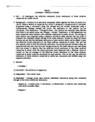
First set up the circuit shown above. In order to this connect the power pack, the ammeter and the 3 resistors in a series circuit using some connecting wire. Then connect three voltmeters across each of the three resistors and then finally connect the 4th voltmeter (Vs) across all three resistors and all three voltmeters (as shown above).
- Now set the current in the circuit to 150 milliamps using the power pack and the ammeter.
-
Quickly take the readings for the voltage across each individual resistor (V1, V2 and V3) and the combined voltage across all three resistors (Vs).
- Now repeat the above step until you get 4 sets of readings for each value of the different voltages.
- Next repeat the entire above procedure using a different value of current (200 milliamps)
-
Now for each value of current separately calculate an average value of the voltages on V1, V2, V3 and Vs.
-
Using the average values of V1, V2, V3 and the value of the current calculate the values of resistance (R1, R2 and R3) for the three resistors, with both values of current, respectively.
-
Now add the individual values of resistance (R1, R2 and R3) for the three resistors, with both values of current, to get the value of the effective resistance.
-
Using the respective value of Vs and the value of the current in both cases, calculate the value of the effective resistance (Rs) for the entire circuit and cross check with your above answer.
Raw data table showing all four trials of the voltages V1, V2, V3 and Vs for both values of the current.
Processed Data Table showing all the values used to calculate the effective resistance of all the three resistors by both processes for both values of current along with the overall average value of effective resistance.
- Graphs of Results – Refer to attached graphs sheets for the graphs of the results.
-
Observation – Thus, from the above results we can observe that from the readings of our experiment the average effective resistance of the three resistors connected in series is approximately 40 ohms, this can be seen from the two values of this quantity which were obtained from the experiment, 39.375 ohms and 40.271. The average values of resistance for the three resistors R1, R2 and R3 can also be observed to be around 8.5 ohms, 6 ohms and 25 ohms respectively.
- Conclusion – Thus from the above experiment we can conclude that the effective resistance of the 3 resistors connected in series, using both ways, was approximately 40 ohms. This can clearly be seen from both values of the average effective resistances, calculated separately.
- Fair Test –
In order to conduct the experiment in a fair manner, I took the following measures.
- I used the same apparatus through out the experiment.
- I measured all the readings of voltage carefully so that the readings were as accurate as possible.
- I made sure that all measuring instruments were at 0 before they were used.
- I made sure that the circuit was securely and properly set up.
- I tried to keep the current reading as accurate as possible.
- I made sure that the wires would not heat up too much by keeping the circuit switched off as much as possible.
- I took four trials of each voltage reading for both sets of to get a more accurate average set of results.
- Safe Test –
In order to conduct the experiment safely, I took the following measures.
- I handled all the apparatus carefully so that no one was hurt and so that no apparatus was damaged, the resistors were handled with special care.
- The circuit was always kept off when not in use.
- The work space around me was clear so that there were no accidents and so that the experimental setup was intact.
- Factors that could have led to experimental inaccuracies–
The factors, which could have affected the experiment negatively thus causing any experimental inaccuracies, are given below.
- A slight error while measuring the volatges could have led to anomalies.
- The current flowing through the circuit could have been slightly more or less than required, thus leading to inaccurate results.
- While keeping the circuit on for too long the wire could have heated up thus affecting the resistances in the circuit.