Jigsaw redesign. We were assigned the task of evaluating and redesigning a given DIY tool a Jigsaw model for re-launch to the market. While examining the tool it became clear that there were many problems with the current design compared to that of other
Dept of Mechanical & Manufacturing Engineering
Trinity College Dublin
3MEMs3. Design II. Group Redesign Report
RED TEAM
Robert Young 07599242
Greg Withey 07******
Jessica Nelson 07******
Eoin Kearney 07383002
Contents
. Introduction
2. Redesign process
3. Section 1
3.1. Initial assessment
3.2. Market research
3.3. Target Market
3.4. Customer research
3.5. Conceptual
3.6. Ideal Jigsaw concept
4. Section 2
4.1. Disassembly
4.2. Bill of materials
4.3. Exploded view
4.4. Technical aspects
4.4.1. Electric motor
4.4.2. Electronics
4.4.3. Gearing
4.4.4. Bearings
5. Section 3
5.1. redesign
5.1.1. Pendulum removal
5.1.2. Blade attachment
5.1.3. Shoe
5.1.4. Dust extraction
5.1.5. Ergonomics
5.1.6. Safety
5.1.7. Other changes
5.2. Manual
5.3. Re marketing
5.4. Summary
6. Conclusion
7. References
. Introduction
We were assigned the task of evaluating and redesigning a given DIY tool a Jigsaw model for re-launch to the market. While examining the tool it became clear that there were many problems with the current design compared to that of other jigsaws on the DIY market and that it contained unnecessary and not required extra functions. We began by dividing the required project work in a way that all agreed fair and to exploit what each person could do best.
We conducted regular team meetings to update team members on our individual progress and insure we hadn't lost sight on the task. At these meeting any problems encountered were discussed, new emerging problems and tasks were assessed and assigned. New ideas were listened to even if they seemed farfetched at first.
The final goal from all of this was to design a better engineered jigsaw that was more attractive to our target market and most of all safe to use. All the time cost variables would be minimized while any added features would be balanced of by the savings elsewhere.
2. Redesign process
Stage 1
Assessed initial product and its current problems, while coming up with out of the box solutions
* Initial assessment to determine flaws
* Initial division of tasks
* Experiments to evaluate performance
* Formulation of function structure
* Customer research through surveys
* Market research patents other products on the market
* Analysis of research
* Formulation of random ideas for changes to the jigsaw
* Came up with the concept of the ideal jigsaw
* Bringing the project to the reverse engineering stage
Stage 2
Redesign process began, with a breakdown and in-depth look at internal workings and functions of the device.
* Second breakdown of project work
* Examination of regulatory issues
* Disassembly and analysis of product configuration
* Bill of material
* Analysis of function of each individual part
* Analysis of necessity and practicality of each individual part
* Technical analysis of tool piece function
* Reduction in part count and removal of unnecessary parts
* Improvement in ergonomics
* Formulation of individual and group redesign ideas
* Proposed redesign
* Calculations and analysis
* Final redesign
Section 1
3.1 Initial assessment
Jessica:
We took note of our first impressions on opening the box so that we could refer back to them after we have finished redesigning the jigsaw. My intial impressions were that the bow was not appealing and the pieces inside were loose and not packaged well, maybe bubble wrap could be used for protection. The tool itself did not look complicated but quite simple to operate. It looked quite flimsy and like it could easily break if dropped. There were not many piece in the box. The plastic bag could have been a choke hazard and there were no warning signs for that. The rubber handle on the tool looked as if it would peel off after little use and the symbols on the buttons looked likely to peel off too.
Greg:
Initially I felt that the box was a bit dull and perhaps lacking in technical information. I was surprised when we opened the box to find a number of loose parts just lying around in the box. Something could easily have got lost. With regards to the saw itself I felt that it was generally quite badly finished with the seam and the laser button in particular looking poorly made. I also noticed that there were a number of buttons on the saw with no indication on them of what they did. The guide continued in the same vain with it being badly written with illustrations even in the wrong places. I also found it strange that nowhere was there a sign telling users to read the manual before using the saw. Overall I felt that there were a number of areas that needed to be redesigned.
Keith:
My initial impressions of the jigsaw were gathered from the quality and type of packaging the jigsaw was presented in. The box looked fragile, with some sealing tape already removed from it. This I gather could have been from poor packaging and handling or due to the weight of the jigsaw in relation to the quality of the box. It was made from cardboard box and was prone to moisture and water damage. The colors chosen were neither luminous nor attractive at first sight. The design of the box could have been made more appealing, possibly by using a different font and color scheme. The components that came with the jigsaw were also loose and fell right out of the box which could be easily lost and may cause hazard. The Jigsaw looked robust though with stains of glue in some places where touch up work had been done.
Robbie:
Fist impression was that all the contents in the box were completely loose and free to move about. Not an ideal solution for transport and not very professional first impression. Also the information on the side of the box wasn't helpful to me in making a decision. 800w was there but I had no idea if this was a advantage or advantage or how it compared in the market. I was impressed with the warranty and after sales support. I was impressed with the laser option on such a cheap model and the overall robustness of the jigsaw too seemed up to scratch in my initial opinion .
3.2 Market Research
When given the task to redesign any type of product, be it a power tool or a water bottle, the aim of redesign is to make it a more desirable product for the customer and therefore sell more of the product.
In order to redesign and improve this jigsaw we must take a look at the top selling jigsaws on the market to see why it is they are selling. This tells us what the customer is looking for in a jigsaw and what our competition on the shelves is.
We have been given a price range of about seventeen to twenty-three euro in which this jigsaw is allowed to sell for. So it seems obvious that we are to look at the jigsaws on the market within this price range. But why not look into the more expensive price range? This way we can hopefully incorporate more advanced ideas and designs into our own for better selling points.
We decided to take a look at three different price ranges.
These were
* The cheap and simple to use jigsaws, €15-€30.
* Advanced jigsaws of €40-€90.
* Heavy duty jigsaws that range in the hundreds of Euros.
Cheap (€15-€30) jigsaws
Many reviews and opinions of professionals and non professionals suggest that the cheaper jigsaws use less precise blades that are fine for rough cutting. They are used at home by non-professionals and first time users, often to cut thin sheets of wood or metal. They are light in weight and come with step by step instruction manuals that often lack in-depth safety instruction. The typical cutting depth by a cheap jigsaw varies on the material;
* Metal: 4mm-10mm (depending on the metal e.g. Ferrous, or non-ferrous)
* Wood: 50mm-80mm
Make/model
Tesco Jigsaw
Performance Power
PJS550
Black and Decker (CD301T)
Available at
Tesco
B&Q
Woodies
Price(€)
4.99
22.99
26.99
RPM
500-3000
800-300
Single speed
Dust Extraction
Yes
Yes
Yes
Blade type
T-shank (1 for wood cutting)
T-shank(2 supplied)
Power(watts)
350
555
370
Extras
* Pendulum action
* Dust tube
* Adjustable blade plate
* 2 year guarantee
* Soft grip
* 2 colours available
* Lock on switch
* Pendulum action
* Tool free blade clamp
Cutting depth(wood)
80mm max
65mm
55mm
From the table shown above, it is clear that even in the cheap price range there are a number of features that each jigsaw has. In the cheap price range the main features include:
* Variable speeds
* Dust extraction method
* Pendulum action.
Although this may seem like some great extras to have, the dust extraction method and the pendulum action often don't work very well. As well as that, the people who buy such cheap products often don't even know what the pendulum action is or how to use it.
Advanced jigsaws of €40-€90
These jigsaws can vary greatly from the cheaper price range. They are heavier and sturdier, built for more experienced users and for more frequent use. They have deeper cutting depths and due to the more sturdy build, the user experiences less vibration and can therefore work for a longer period of time with the tool. The actual design of jigsaws in this price range change also. There is the typical overhand design and also the barrel grip. These are shown below
Overhand Grip:
Barrel Grip:
The features that can be expected with the jigsaws in this prices range are as follows:
* Laser guide
* On board blade storage
* Parallel cutting guide
* Cordless
* Comes with many blades for both metal and wood cutting
* Accepts both t-shank and u-shank blades
* Dust extraction method
Heavy duty jigsaws (>€100)
These jigsaws, although very expensive, do not have that many more feature than the previous price range. They are made for use by professionals. They are heavy and sturdy, made to be used long hours in a work shop every day. They also have great ergonomics in order to make it as easy and comfortable to use as possible. The cuts they make are very precise in both mood and metal. The cutting depth for these machines range from:
* Metal: 20-30mm(steel)
* Wood: 130-150mm
Heavy Duty Dewalt Jigsaw
3.3 Target Market
After doing the market research and taking into consideration the cost parameters of the redesign project, we decided on what our target market should be and what it is we think they want in a jigsaw. This is what we decided:
* Rough (non precision cutting)
* No skill or training required
* Plug in and go (easy to follow manual)
* Affordable
In order to meet out target market's needs, we need to do our customer research.
Long term vision: To manufacture a product that customers feel confident in buying and using
Competitive advantage: Complete our market research to insure we are at the same standard as our competitors.
Target Market needs: Complete customer research to make sure our customers have exactly what they want and need
3.4 Customer Research
There are five basic methods of customer research
* Surveys
* Focus Groups
* Personal Interviews
* Observation
* Field Training
As we were not able to carry out each of these five methods, we did use two of them, Survey and field training.
We drew up a survey between the five of us, each suggesting questions that we thought would be relative to ask. A sample of the survey is given at the end. We allowed for two types of questions, dichotomous, where the respondent has two options i.e. "Yes" or "No", and Continuous, where the respondent is presented with a continuous scale . The survey was made out in a simple tick the box style. Each continuous question could be answered on a grade of 1 to 7. 1 is equal to being very bad and 7 is excellent. We used this grading system because a grading from 1 to 10 allows too many options for the person taking the survey and we get a less accurate result of how the tool really performed. As well as questions there was also space allowed for people to write in their own personal opinions. Here is a sample question
How did you find the laser?
(bad)
2
3
4
5
6
7(excellent)
We each gave the jigsaw and survey to our friends and family. This resulted in us getting both professional and non professional opinions and answers. As a result, we decided to weight the people and the answers. The professionals got a weighting of 1 and the non-professionals got a weighting 0.6. This is because a professional's opinion and view on a question such as the dust extraction method is far more valid as he/she would understand what an acceptable amount of dust extraction is. The questions were also weighted because a question such as "Do you find it safe to use?" is far more important that "Do you like the colour?"
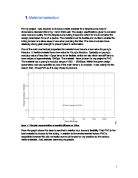
Here is a chart showing the average value for the most important questions.
Key:
. Ease of use
2. Handling
3. Changing Blades
4. Mitre angle
5. Laser
6. Parallel guide
7. Dust extraction
8. Functionality
9. Over all look
0. Build quality
1. Button positioning
It can clearly be seen that the dust extraction method and the changing of blades was a major problem. These are both highlighted in red and are well below average.
In conclusion to our survey, from both questions answered and the users extra comments we found that the main problems were:
? Difficulty with changing Blades
? Dust gets inside tool
? Pendulum motion not needed
? Laser is no good
? Bad weight distribution
? Bigger safety guard needed
? Better labelling on buttons required
? Build Quality was bad
? Not enough safety information in instruction manual
00% rated it as good value for money spent.
So clearly this means that we need to try and stick to the price range that we have currently but that we definitely need to improve the overall look and feel of the tool.
4
3.5 Conceptual Design
Step 1: Clarifying the task elaborating on the specifications.
Before beginning to design anything there are a few key issues that need to be examined. Some questions that need to be explored right from the start are:
* What is Jigsaw?
* Who is it designed for?
* What exactly is required from the jigsaw?
The first question is easy to answer. Bosc define a jigsaw as a tool used for cutting arbitrary curves, such as stenciled designs or other custom shapes, into a piece of wood, metal, or other material. It can be used in a more artistic fashion than other saws, which typically only cut in straight lines. In this way, it is similar to the rasp and the chisel. Although a jigsaw can be used to cut arbitrary patterns, making a straight cut freehand is difficult even with a guide.
In case of the second question, the jigsaw is being designed for the DIY market which therefore has significant effects on the ease of use and safety elements of the device.
The final question is what is required from the jigsaw. In its essence the answer is that the jigsaw needs to be safe, easy to use and to cut the material at a constant force with ability to cut in straight lines and at angles with even cuts and without damaging the material. However these are only the requirements in their barest form. There are a number of other constraints which will now be looked at.
One of the best ways to visualise these constraints, in a more formal manor, is to draw up a table of formal specification. This is shown in figure 1 below. It is worth noting that some of these restrictions were given in the question sheet while others required some deeper thoughts and ideas on the subjects. The table lists all the possible constraints and assigns them a letter, D or W, respectively. D is a demand of the pump and W denotes a wish that would be nice but is not essential.
Specifications
Changes
D/W
Requirements
Resp
Geometry
D
Must be ergonomic to the human hand
W
Must be easy on the eye
D
Must be securely encased
D
Must be light enough to hold in one hand
W
Must be easy to hold and press switches
Function
D
Must be efficient enough to maintain constant cut rate
W
Must be quiet
D
Must be able to stay cool while running
W
Must have a low weight to power ratio
W
Must be power efficient
D
Must be able to cut in straight and angled lines
Reliability
D
Must be reliable and robust
W
Parts must be easily interchangeable
D
Must not stop working
D
Must resist corrosion (Particularly rust)
Production
W
Must be easy to produce
W
Must be able to be mass produced
Safety and Ergonomics
W
Design must be as simple as possible
D
All moving parts must be covered
W
Working principle of product environmentally sound
D
Must satisfy all safety regulations and codes of quality
Operations and Maintenance
W
Must be easily cleaned and maintainable
W
Parts must be quite when running
W
Should be no complicated controls
D
Must have an on/off switch
Costs
D
Device must cost less than €20
Energy
D
Must have efficient motor
D
Motor must not overheat
Patents
D
Must not be a patented design
Shelf Life
D
Must have a stated shelf life
Step 2: Abstracting to identify the essential problems
In this step the broad list of requirements listed above needs to be reduced to figure out the key to the design. The list needs to be shortened and the most important factors extracted. Then a more qualitative approach should replace the previous quantitative one. Finally the problem should be generalised and formulated in solution-neutral terms so that the search for a solution is not prejudiced.
This process can be summarized into a number of key points:
* The jigsaw must cut the material at a steady rate with even cuts
* Must have an on and of switch and a switch for angled and straight cutting
* Must be up to safety standards and regulation
* Must have a strong motor that doesn't overheat and is not too load when running
Step 3: Establishing the Function Structures
Breaking down the main functions
Step 4: Searching for Solution Principles to Fulfill the Sub-functions
This is the step where the designer begins to get more creative. Now that we know what is required from the jigsaw we can start to look at some possible solutions. It is important to note that at this stage all designs are of the conceptual form. This is in effect a brainstorming phase and means that in the initial stages it is more important to come up with a number of possible designs rather than to be come focused on just one. Any solution can be considered in this stage and only later on will they be looked at in a more critical light.
When searching for a solution the most common methods are to use literature searches, or an analysis of existing designs, as well as various brainstorming techniques.
Insert structure diagram
Steps 5 and 6: Combining solution Principles to Fulfill the Overall Function
In these steps the aim is to look at all the different design variables and initially see which are compatible together. In our case however, the diagram below shows, that almost all of the options are suitable to be used with each other.
We analysed the subfuctions to come up with ideas for ...
This is a preview of the whole essay
When searching for a solution the most common methods are to use literature searches, or an analysis of existing designs, as well as various brainstorming techniques.
Insert structure diagram
Steps 5 and 6: Combining solution Principles to Fulfill the Overall Function
In these steps the aim is to look at all the different design variables and initially see which are compatible together. In our case however, the diagram below shows, that almost all of the options are suitable to be used with each other.
We analysed the subfuctions to come up with ideas for redesign that would not normally come to mind.
3.6 Perfect Jigsaw
After the customer feedback from surveys, the market research and our own group discussions we were in a position to look at what we felt was the perfect jigsaw. This is the tool that with no cost constraints would fulfil all its functions perfectly.
The ideal jigsaw obviously may not be a viable design as it may exceed practical costs and go beyond what is expected of a jigsaw but it enabled us to look at the tool in a new way. We could take the crucial elements from the ideal jigsaw, compare them with those of our jigsaw and maybe find simple ways to redesign our own jigsaw to improve its overall functionality and quality.
The Following were perceived to be the 'ideal'
A jigsaw in simple terms is used for cutting arbitrary curves, such as stenciled designs or other custom shapes, into a piece of a material. The cut on a microscopic level would not be straight. Higher quality blades in both material and sharpness would lead to straighter cuts.
The ideal jigsaw would be as light as possible without affecting its functionality too light a jigsaw would lack the weight to maintain stability and lead force needed in cutting.
The use of an additional handle towards the front, to facilitate leaning over to see the cutting of the work piece, that would increase user comfort and help make the jigsaw more productive. It would have perfect grip and an adequate hand size for any user.
We thought about whether our jigsaw should be cordless powered by a battery as this would avoid the annoyance of cables in both length and getting in the way. Ideally a decent long life high power battery with a high charge cycle time. The cordless option would naturally make the jigsaw easier to store, which is ideal in a domestic home where it may not be frequently used. New lithium Ion Batteries used in the in similar can deliver high power for extended time periods. In reality the cost is too great and to optimise cost and functionality the chorded option must be kept.
One thing, which we have discussed in depth, is the method and options available for how and where the waste is extracted to. In an ideal situation, there would be an option for which direction the dust would come out and there would be an attachment to remove it neatly. From our research, we have found that this it is an important factor for the target customer and so it could be an important redesign feature. Safety is a key aspect in our concern in this as woods produce dust and some of these dusts are harmful if inhaled without proper protection, therefore it would be recommended that the perfect jigsaw have numerous safety masks provided and a pair of safety glasses.
The jigsaw must have an adequate safety lock switch that cannot so easily be held on as this is a obvious serious safety concern a child should not be able to turn on the jigsaw so easily. An adequate safety lock switch would prevent accidents and be up to standard for all regulations specific to a jigsaw and an electric power tool.
Our manual that would accompany the jigsaw would have good clear detailed instructions, which are easy to understand, and would be available in several languages. These instructions should have in depth safety warnings in relation to toll operation and detailed instruction on operation required maintenance and storage. Our jigsaw would be aesthetically pleasing and affordable while being reliable and of high quality.
The ideal jigsaws packaging should be attractive to the user contain some basic instructions as it is not that unlikely for the manual to be lost. An idea on what the jigsaw would be used for would also be of benefit in encouraging a consumer to buy it
.
Optimising the human factors such as reduced noise levels and vibration emissions in an ideal world would be done to a minimum without compromising the performance.
Looking at our tool while comparing it to our ideal jigsaw highlighted which aspects of our tool we should focus on redesigning. We discussed focusing on improving the dust extraction method highlighting what qualities it really requires. So these problems must be fixed if it is possible to do so without affecting the functionality in a negative way.
The inclusion of all out "ideal design" ideas should be looked at discussed and compared with the user feedback survey. Then the relevant design features should be accommodated to maximise the performance and usability of the jigsaw as well as optimising the overall part placement to ensure an user friendly ergonomic design. It is no good having all the features needed for the "perfect jigsaw" when in reality all there is a device that cannot be used.
4.4.1 (a) The Electric Motor
The electric motor in the Power Craft Jigsaw is an AC motor. In our case, it is an 800Watt jigsaw capable of supplying 0-3000RPM. It is commonly used in power tools due to its characteristics regarding the power it can deliver relative to its size and weight.
The AC motor is driven by alternating current supply. It consists of two basic parts, an outside stationary stator having coils supplied with alternating current to produce a rotating magnetic field, and an inside rotor attached to the output shaft that is given a torque by the rotating field.In the figure above we see the arrangement of the components that make the AC motor. There are two types of AC motors, depending on the type of rotor used. The first is the synchronous motor which rotates exactly at the supply frequency or a submultiple of the supply frequency. The magnetic field on the rotor is either generated by current delivered through slip rings or by a permanent magnet. The second type is the induction motor, which runs slightly slower than the supply frequency. The magnetic field on the rotor of this motor is created by an induced current.
AC motors also come with various speed ratings. Speed is usually specified as rotations per minute (RPM) at no load condition. As the motor is loaded down, the speed will slow down. When the AC motor is running at its rated power draw, the speed of the shaft measured in RPM is the full load speed. If the electric motor is loaded too heavily, the motor shaft will stop hence in our design we will keep the same motor size as it did not stall or seize during use yet providing the required amount of power. Costs are also maintained by not moving up to a more powerful motor.
Calculations for the Motor
To calculate motor full-load torque:
Where:
T = torque (in lb-ft)
HP = horsepower
5252 = constant
rpm = revolutions per minute
Therefore we need the horse power:
800Watts = 0.072 hp
Therefore:
=0.126048 lb/ft
= 0.1708981409616 Nm
4.4.2 (b) Electronics
Capacitors
A capacitor or condenser is a passive electronic component consisting of a pair of conductors separated by a dielectric (insulator). When a potential difference (voltage) exists across the conductors, an electric field is present in the dielectric. This field stores energy and produces a mechanical force between the conductors. The effect is greatest when there is a narrow separation between large areas of conductor; hence capacitor conductors are often called plates.
An ideal capacitor is characterized by a single constant value, capacitance, which is measured in farads. This is the ratio of the electric charge on each conductor to the potential difference between them. In practice, the dielectric between the plates passes a small amount of leakage current. The conductors and leads introduce an equivalent series resistance and the dielectric has an electric field strength limit resulting in a break down voltage.
Capacitors are widely used in electronic circuits to block the flow of direct current while allowing alternating current to pass, to filter out interference, to smooth the output of power supplies, and for many other purposes. They are used in resonant circuits in radio frequency equipment to select particular frequencies from a signal with many frequencies.
Redesign cautions we heeded to when using capacitors:
) When protecting switching contacts, always include a resistor in series with the noise suppression capacitors
2) Noise suppression capacitors are most effective when located close to the offending noise source. Excessive lead length may cause abnormal oscillation and decrease the energy absorption capability of the capacitor.
3) Noise suppression capacitors are specifically designed for standard line frequencies and should not be used in circuits where normal operation will exceed 70Hz.Whereas our jigsaw has the frequency rating of 50Hz
Some applications of Capacitors
The following list shows some of the uses of capacitors:
AC Motors, Machine Tools, Contact Protection, AC Line Suppression, DC Motors ,Washers, Industrial Controls, Vacuum Cleaners, Brush Motors ,Power Supplies, Robotics ,Tumblers, Grinders ,Automotive ,NC Controls ,Electric Switching, Motor Controls ,Lighting, CNC Controls, Power Snubbers, Mixers ,Frequency Controls, Antenna Coupling, Mechanical Switching,
Noise filters and suppressors
The Iron Coils. (Noise Suppression)
Electrical noise, which affects the correct operation of electrical equipment, can originate from sources both external and internal to the product. For example, high frequency noise can be generated by the rotation of a brush motor. As a counter measure to such noise, a capacitor can be introduced into the noise prevention circuitry to lower the circuit impedance. It is necessary to use a capacitor with excellent, high-frequency characteristics. This is why metalized polyester film is used in most cases as the capacitor dielectric in AC noise suppression capacitors. As in the case of the Jigsaw, a capacitor is used to suppress the noise from the motor.
In the case of our jigsaw, a metal coil is also used to compose a filter circuit as a means of improving attenuation and expanding band range. This method also acts as a noise suppression mechanism. Noise suppression capacitors are most widely applied as countermeasures to noise occurring in inverters, switching power units, brush motors, and to the full range of office automation equipment.
RFI interference
Interference comes from the interaction of the commutator and the brushes during the motors operation. Also there will be some interference from the power supply itself.
The elimination of interference caused by a-c commutator motors , especially radio interference elimination in auxiliary motor vehicle motors , is accomplished, as is well known, by interference elimination inductances connected in series with the brushes and/or interference elimination capacitors arranged in series and parallel to the armature circuit branch of the commutator motor. The interference suppression prevents the high voltage peaks between the brushes and the commutator from causing interference with the surroundings and also with the on board circuitry in the planer.
The electronic filters have to be able to withstand ongoing high voltages and voltage surges and spikes for years, and if they fail, they should not explode, catch fire or put people at risk of shock.
The EMI suppression circuit will have some overall reactance. This reactance will change with frequency. Since the commutator and brushed will give off sparks then the voltage needed to be suppressed will have a given frequency. The EMI circuit must be tuned to maximise dissipation of this induced RF noise at the commutator. Unfortunately we have no data as to the ability of the circuitry to actually carry out this function. There are many specialised EMI filters available but they are expensive and we are moving forward on the assumption that the current circuitry is sufficient.
TRIAC
Figure 3: Example of a triac Figure 4: Triac schematic symbol.
A TRIAC, or Triode for Alternating Current is an electronic component approximately equivalent to two silicon-controlled rectifiers (SCRs/thyristors) joined in inverse parallel (paralleled but with the polarity reversed) and with their gates connected together. The formal name for a TRIAC is bidirectional triode thyristor. This results in a bidirectional electronic switch which can conduct current in either direction when it is triggered (turned on) and thus doesn't have any polarity. It can be triggered by either a positive or a negative voltage being applied to its gate electrode. Once triggered, the device continues to conduct until the current through it drops below a certain threshold value, the holding current, such as at the end of a half-cycle of alternating current (AC) mains power. This makes the TRIAC a very convenient switch for AC circuits, allowing the control of very large power flows with milliampere-scale control currents. In addition, applying a trigger pulse at a controllable point in an AC cycle allows one to control the percentage of current that flows through the TRIAC to the load (phase control).
Application
Low power TRIACs are used in many applications such as light dimmers, speed controls for electric fans and other electric motors, and in the modern computerized control circuits of many household small and major appliances. In our Jigsaw project it is used as the speed control mechanism.
However, when used with inductive loads such as electric fans, care must be taken to assure that the TRIAC will turn off correctly at the end of each half-cycle of the AC power.
For higher-powered, more-demanding loads, two thyristors in inverse parallel may be used instead of one TRIAC. Because each SCR will have an entire half-cycle of reverse polarity voltage applied to it, turn-off of the SCRs is assured, no matter what the character of the load. However, due to the separate gates, proper triggering of the SCRs is more complex than triggering a TRIAC.
In addition to commutation, a TRIAC may also not turn on reliably with non-resistive loads if the phase shift of the current prevents achieving holding current at trigger time. To overcome that, pulse trains may be used to repeatedly try to trigger the TRIAC until it finally turns on. The advantage is that the gate current does not need to be maintained throughout the entire conduction angle, which can be beneficial when there is only limited drive capability available.
(http://en.wikipedia.org/wiki/Triac)
Thyristor
The thyristor is a solid-state semiconductor device with four layers of alternating N and P-type material. They act as bistable switches, conducting when their gate receives a current pulse, and continue to conduct for as long as they are forward biased (that is, as long as the voltage across the device has not reversed).
The thyristor is a four-layer, three terminal semiconducting device, with each layer consisting of alternately N-type or P-type material, for example P-N-P-N. The main terminals, labeled anode and cathode, are across the full four layers, and the control terminal, called the gate, is attached to p-type material near to the cathode.
4.5.3 Standard Gears
There are many types of gears in today's world. Ranging from the tiny gears inside analogue watches to gears on bicycles to huge gears on industrial machines gears play a key role in modern society. The following section is a brief summary of some basic types of gears which are taken from Mr C G Lyons notes.
Spur gears
These are cylindrical gears and are the most common form of gear drive. The teeth are straight and parallel with the axis of rotation. The efficiency of the spur gear can be as high as 90 per cent and it is capable of practical speed ratios up to 10:1, although 6-7:1 is more usual. The main disadvantage of spur gears lies in the fact that they tend to be noisy at over 300 metres/min.
Single helical gears
Helical gears are produced by cutting the teeth an angle to the gear axis and the teeth follow a spiral path, thus making for gradual tooth engagement and load distribution; efficiencies as high as that for spur gears are possible. Ratios up to 10:1 can be handled and greater loads are possible than with the spur gear. A degree of axial thrust, however, is produced by the single helices and this must be catered for in the bearing design. Single helical gears can be used at speeds up to 1200metres/min.
Double helical gears
Commonly specified when (a) axial thrust from single helical gears would be too large. (b) Plain bearings are used. To balance side thrust, the teeth are formed on each gear in helices of identical angle but opposite hand. Single reductions of 10:1 with double reductions of 75:1 and treble reductions of 350:1 are used. Pitchline velocities from 1200 to 6000 metres/min are possible, depending on accuracy of manufacturing methods and other factors.
Bevel gears
Bevel gears are for situations where it is desired to transmit motion between two shafts whose axes intersect. The tooth action is similar to that of spur gears, being a line contact parallel to the pitch line. Thrust bearings must therefore be provided. The maximum gear ratio for straight bevel gears is 4:1.
Spiral bevel gears
The spirally cut bevel gear, like the helical gear in its relation to the straight spur gear, can withstand higher speeds than the straight cut bevel gear and is quieter in action. The gear ratio can be as high as 9:1. Pitch line velocities of 300 metres/min maximum can be handled.
The Gears Used in Our Jigsaw
In our jigsaw there is one main gearing unit. It is used to change the angular motion of the motor into the reciprocating motion required by the blade. It does this by making use of a cam attached to the larger gear.
The gears used are single helical gears. The small cog, which is attached to the motor, has 5 teeth while the larger cog, which has the cam on it, has 46 teeth. This means that the gear ratio is 46:5 which equates to a ratio of 9.2:1. This satisfies the 10:1 ratio that is stated above.
Helical gears are different to spur gears because the teeth are angled. The angled design of the teeth causes them to engage each other differently. As helical gears come in contact with one another, their level of contact increases gradually, rather than engaging the entire tooth at once. In mechanical systems, this contact causes less impact loading and provides smoother, quieter operation. Helical gears are also stronger and longer lasting than spur gears.
There are a number of important measurements that should be considered when selecting helical gears. Like other gears, a helical gear's numbers of teeth, pitch diameter, outside diameter and centre distance are all factors in its performance and effectiveness. Helical gears also have centre angle and tooth angle measurements, which help define the nature of the gear. Interestingly, if aligned correctly, properly matched helical gears can be used to drive perpendicular shafts, although they are typically used to transmit power between parallel shafts.
There are both single and double helical gears. Single helical gears are the most familiar type, and consist of a single line of angled teeth around the perimeter of the gear. Double helical gears use two tracks of mirrored, angled teeth. These tracks are often separated by a gap for different machining purposes, but can be in direct contact with one another (continuous double helical gears). Double helical gears are stronger than single helical gears and have zero sideways force. In our case the single type is used. This is because they are cheaper, take up less space and in our case we don't require the added strength that the double variety would provide.
Gearing Calculation
Virtual Number of Teeth:
Another advantage of helical gears over spur gears besides quiet operation is their relatively stronger teeth for a gear with the same normal pitch, pitch diameter, and number of teeth. We can define a virtual number of teeth Ne:
This defines a virtual gear that is equivalent to a spur gear with Ne teeth thus giving a stronger tooth in both bending and surface fatigue than a spur gear with the same physical number of teeth as the helical gear. The larger number of virtual teeth also reduces undercutting in small pinions, allowing a lower minimum number of teeth for helical gears than for spur gears.
4.5.4 The Bearings
Bearings play a key role in any mechanical tool. They allow two surfaces to rub against each other while causing minimal friction. There are many types of bearings. Some examples are plain bearings, rolling element bearings, jewel bearings, fluid bearings, magnetic bearings and flexure bearings. They all have different properties and are used in a variety of different ways.
In the jigsaw there are a number of bearing which all have important roles to play. There are two ball bearings at each end of the rotating part of the motor as well as a cylindrical roller bearing and a plain bearing in the gear itself.
The ball bearings used to support the motor are single row deep groove ball bearings.
The schematic shows a cut-away view of single row deep groove ball bearing:
The product codes for the 2 bearings are 607zz for the bearing at the front end of the motor and 608zz at the back end. The manufactures code is cxza. After extensive research we were unable to find any information relating to that code. The closest we could find was a reference to it on page 23 of a Sun Hydraulics product information sheet.
Despite this set back we were able to locate the product codes on a competitor's website. VXB bearings give the following information on each of the bearings.
Item: 607ZZ
? Dimensions: 7*19*6 mm/Metric
? ID (inner diameter)/Bore=7mm
? OD (outer diameter)=19mm
? Width/Height/thickness=6mm
? Type: Deep groove ball bearings
? Material: Chrome Steel
? Shielding: 2 Metal Shields
Item: 608ZZ
? Dimensions: 8*22*7 mm/Metric
? ID (inner diameter)/Bore=8mm
? OD (outer diameter)=22mm
? Width/Height/thickness=7mm
? Type: Deep groove ball bearings 608ZZ
? Material: Carbon Steel
? Shielding: 2 Metal Shields
For more specific product information we were referred to the skf bearing manufactures site the Mr. Lyons sent us. Using the dimensions already known we could locate the bearings.
607zz Bearing:
608zz Bearing:
The following 2 diagrams show a 3D sketch and a wire frame model of the specific bearings in question.
FATIGUE LIFE
BASIC BEARING FATIGUE LIFE
The basic fatigue life of a rotating deep-groove ball bearing is given as:
C
P
3
.
06
revolutions
L10=
where:
L10
=
rated fatigue life with a statistical reliability of 90%
P
=
bearing equivalent load
C
=
basic radial dynamic load rating (see individual bearing selection charts)
The formula to calculate the lifetime of a bearing is:
Where: Cr = The dynamic load rating
Pdes = The design load
N = rpm pf the shaft inside the bearing
Therefore we need to know these three things. The Cr value is given in the bearings section of this report and we are going to assume a design load of 15kg. This means we need to find the rpm for the motor.
rpm = 120 x F
P
Where: F = supply frequency (in cycles/sec)
P = number of motor winding poles
Therefore rpm = 120 x 50hz
2
= 3000
So now we have everything needed to calculate the lifetime of both bearings.
The 607zz bearing:
The Cr value is given as: 2.34kN
Therefore:
If we assume that the average jigsaw would only be used for a maximum of 5 hours a day that means that our jigsaw can be used for 280 straight days.
This is clearly enough time for a cheap DIY jigsaw so we will not need to make any changes to the 607zz bearing.
The 608zz Bearing
The Cr value is given as: 3.45kN
Therefore:
This is a longer lifetime than the 608zz so clearly does not need to be changed either. For this reason we will leave the bearings in our jigsaw as they currently are.
5. Section 3
5.1 Redesign
5.1.1 Pendulum removal
One of the main findings to come out of the surveys was that most of the inexperienced users i.e. those that are in our target market, were unable to recognize or understand the function of the pendulum action. The manual failed to explain why one might need to use the function and for what setting was best.
From the disassembly and subtract process it was also noted that the pendulum function of the jigsaw required extensive parts and introduced a whole new plane of movement within the jigsaw. This immediately adds complications in terms of reliability and robustness of the jigsaw. Along with the added parts comes extra expenses and costs in manufacturing and thus affects the final market price.
After much deliberation and processing of the advantages of the pro's and the con's it was decided that the pendulum action should be removed for the following reasons.
* Target market did not need this function
* Added reliability issues in extra moving parts
* Took away from the overall robustness of jigsaw
* Added cost in extra parts
* Cost savings by simpler manufactured parts.
The first step in the redesign of this component is to extract all the parts that are involved with the pendulum function from the disassembly process above. Figure 6 shows an isolated view of the pendulum part of the jigsaw. The main shaft is guide and rotated through it's up and down linear motion by an of centre rotating gear on the main motor. Mean while there is a similar linear vertical motion happening at point 1 shown in the diagram which kicks the blade guide forward, hence the blade advances forward on the cutting stroke.
The figure 7 below shows the component breakdown of parts within the system itself. Since the shaft must be allowed move in the forward and backwards plane the tope bearing must be a rose bearing. The lower guide is spring loaded so that the blade will return to rest against the back position when not being kicked forward.
Our proposed redesign of this will mean that the shaft can be fixed to move in one plane only, the reciprocating vertical movement. This allows us to remove and replace many of the parts that are associated with the pendulum movement. This insures that fewer parts will mean a cost saving and reliability increase. The limiting the movement to one plane will increase the robustness and feel of the jigsaw.
The final redesign shown below contains fewer; less complicated parts.
* The shaft and main reciprocating guide (parts 3 and 4) will remain the same.
* The upper and lower shaft guides are identical which will result in lower costs.
* The seal which we found to be unsuitable in the old design and allowed dust into the chamber will be replaced by a better fitting one at no real extra cost.
* The overall combination will result in a secure shaft fixed to move in one vertical plane only.
* Minor changes will have to be made to the plastic casing to allow fitting of new upper and lower guides.
* The lower blade guide on the external of the casing can now be fixed as well and the reciprocating arm used to kick this back and forth removed completely.
5.1.2 Blade attachment
The problems
The current design for the blade attachment was also found to be a major concern from the surveys. Although having a tool-less blade attachment is a huge advantage we felt we could keep this feature but improve on how it worked.
Looking at the research further and from our own experience we saw that the user couldn't define when the blade was firmly held in place. The 3 part process of turning the lock; inserting the blade; releasing the lock seemed like a simple process. It wasn't until we looked closely at the process did we notice the design flaw.
Step two of inserting the blade required the user to apply a considerable amount of force to overcome the spring and push the blade to its definite insertion point. The problem users were having was that they would insert the blade to a certain point below its actual locking position and release the lock. The blade would appear to be held firm however this was not the case.
We took apart the inner components to analyses what exactly was happening and finalized that this indeed was the design problem.
The proposed redesign
The obvious solution to the problem would be to remove the spring however this was need to ensure the blade would always be pushed down against its resting blocks.
The redesign came about by looking at patents that were available online. The simpler designs that need a tool to release and lock were based on the blade fitting into a slot that could specifically fit the T shape. I felt that we could combine this into our design very simply while still maintaining the tool-less blade change feature.
The finalized design incorporates the design seen in the patents by creating an exact fitting slot for the blade. The figure above shows a semi shaft sectioned view. The blade can slide into its slot and the user will not know exactly when the blade has reached its allocated position and stopped against its resting blocks.
To Keep a tool-les locking mechanism I used a design that was similar to the original one. The shape below will allow for the T blade to fit through the widest part when in the open position. However as the lock rotates back the inner diameter narrows and locks the blade in place. The whole mechanism would be spring loaded as the original design and the guide whole for the spring is shown. An upper and lower washer are still needed as per the original design.
The finalized design removes the problem of the user unable to notice when the blade was inserted properly
Fewer parts means lowers cost and more reliable design (2 balls removed and 1 spring).
The Tool-less blade change feature is still kept.
Added cost of machining the shaft to contour of T shape is negligible in the overall cost of the jigsaw and of set against the removal of certain parts.
5.1.3 Shoe & dust extraction
Both the base and the dust extractor were found to be areas of the current jigsaw that needed to be redesigned. After analyzing the problems involved we were able to come up with an innovative design that resolved all the issues relating to both aspects of the jigsaw. This solution will be looked at in greater detail later in this section. However, before we get to this, we need to look at the problems that users found with the extractor and the shoe when using the saw.
The Problems:
We completed our survey and got numerous people to complete it after testing the saw. We used both professionals and amateurs when it came to testing the saw. Their answers were then weighted differently depending on the question.
The Base:
A number of questions were aimed at the handling and feel of the saw. For example:
* How easy did you find the jigsaw to use?
* How easy was it to handle?
The answers to these types of questions as well as some of the comments that we received back gave us an insight into what the problems with the base, or shoe, of the jigsaw were.
The two main problems that arose, in relation to the base of the jigsaw, were:
* It's too small
* It catches on the edge of the work surface
The first problem is obvious and we thought it might be a problem as soon as we opened the box. It is important to remember that the target market for this saw is the amateur weekend DIY-er who will probably hold the saw incorrectly and not be particularly stable when using it. For this reason we clearly need to improve the size of the base.
The second problem was something that we got from our surveys. There were a number of specific comments from people who complained that the base of the saw caught on the edge of the work piece. After looking at the design of the current base it is easy to see why this is:
As you can see from the diagram there are three edges which come into contact with the work piece. The one at the front is raised but the other two aren't. Not only are they not raised but they are actually quite sharp too. Many people found that after initially cutting into the work piece the second edge of the shoe caught the edge of the work piece. This caused the saws movement to stutter, distracted the user and damaged the edge of the piece. It should also be considered that if there were any small surface defects on the wood being cut the sharpness of the edges would probably snag these and make them far worse. Clearly this was an area that needed to be redesigned.
The Dust Extractor:
We felt that the dust extractor on this particular saw was a bit awkward to use so we included a specific question on it in the survey. People were asked:
* How well did the dust extractor work?
In general people scored this section badly. The most common complaint was to do with using the vacuum cleaner at the same time as the saw. People found that with the vacuum attached to the back of the saw they almost had to drag it along while they pushed the saw forward. This is because the average household vacuum doesn't have a long enough length of tubing to adequately be used in this fashion. It was clearly something we needed to consider during the redesign.
Another problem with the dust extractor on this saw only became apparent when we opened it up. The current design sucked the dust up into the saw and along a passage to the back of the saw. While in theory this is fine the passage it followed was right next to all the key moving parts of the saw and it was not particularly well sealed. This was resulting in a large amount of dust being deposited inside the motor and other moving parts of the saw.
This problem is illustrated in the following photographs. They show our saw opened up with the dust channel exposed. The photo on the right clearly indicates the dust channel and the airflow in it. You can clearly see that it is a large area of wasted space and is far to close to the motor and other important moving parts of the saw.
Another problem with the current design is the number of nooks and crannies that are built into the dust passage. They can be seen in the left hand photo above. There are also a number of screw holes in the channel which would impede the exit of dust. There is no need for these and they are simply creating places for the dust to build up which would eventually cause the passage to become blocked.
Finally we noticed that by using the current design there is a large amount of intricate manufacturing which is making to production of the saw more expensive. If we could simplify the design of the passage or remove it completely we could cut down our manufacturing costs. This is something that we were baring in mind when coming up with a better solution.
So once we knew exactly what the problems were we were able to start looking for a solution. We solved the problems for both aspects separately but were then also able to combine them together into one optimal solution. These solutions are now described below.
The Solutions:
Initially we solved both issues individually. We will now look at these solutions.
The Base:
As described above the major issue with the base was its size and shape. For this reason clearly the solution was to enlarge it and improve the design. The diagrams below outline these changes.
As you can see from the diagrams we increased the size to make it more stable and easier to use. It is not possible to know the exact dimensions that would be best without having the ability to produce numerous sizes and have them all individually tested, which was clearly not an option in our case.
Another change than was made was the curling of the edges. This is highlighted in red in the second diagram. In the initial base design only the very front edge was raised. This allowed the following two edges to catch on the edge of the work piece, or any surface defects, and damage it. The new design not only eliminates the two cross supports but it also has rounded edges on all sides so that no damage can occur. The raised edge is even at the back of the shoe. The reason for this is that often amateur DIY-ers will finish a cut and then pull the saw out backwards rather than lifting it out. By curling the trailing edges upwards we can prevent any work piece damage in this scenario.
By eliminating the two cross supports we are saving on money and can therefore use this money to cover the costs of the additional machining required to raise the edges.
Now that the problem of the shoe has been solved it is time to look at the issues surrounding the dust extractor.
The Dust Extractor:
As outlined above one of the main issues that people had with the dust extractor was that they felt like they had to pull their entire vacuum cleaner along with them while using the saw. There is a fairly obvious solution that can be easily and cheaply implemented to make the dust extractor much more user friendly - provide a length of flexible plastic tubing.
This plastic tubing would fit over the nozzle that would be at the end of a standard household vacuum cleaner and would connect directly into the dust extraction port at the rear of the saw. The picture below shows an example of the type of pipe that we would supply.
The details of the pipe that we would provide are as follows:
* Made of Ethylene-vinyl acetate (EVA)
* 1.5m in length
* Flexible
* Cost: < €2
EVA is the copolymer of ethylene and vinyl acetate. The weight percent vinyl acetate usually varies from 10 to 40%, with the remainder being ethylene. It is a polymer that approaches elastomeric materials in softness and flexibility, yet can be processed like other thermoplastics. Good resistance to water, salt and other environments can be obtained but solvent resistance decreases with increasing vinyl acetate content. The copolymers can accept high filler and pigment loadings. Being thermoplastic EVA can be moulded by extrusion, injection, blow moulding, calendaring and rotational moulding. Crosslinking with peroxides can produce thermoset products.
Applications are diverse, such as flexible shrink wrap, footware soles, hot melt and heat seal adhesives, flexible toys, tubing, wire coatings, medical gloves, masks, babies' dummies and bottle teats.
The cost is based on buying 1.5 meter lengths of the tubing in bulk (5000 per order) from the trade website
Another issue that we talked about earlier in this section was the fact that the dust was being drawn through the internal workings of the saw. The solution to this problem is a simple and effective one which combines a new design for both the shoe and the dust extractor.
The Combination Solution:
Rather than having the dust extractor running through the saw we came up with the idea of having it running through a separate external channel. This would be fitted into the gap between the bottom of the saw and the shoe. The schematic and photo representation below show this:
As you can see the dust now doesn't get anywhere near the internal workings of the saw. This has a number of advantages:
* The internal workings of the saw will have a longer life span
* The dust nozzle can be fully removed if not desired
* The manufacturing costs of the saw go down because it is less complex now
* The amount of plastic required to make the casing is reduced which will cut costs
* The saw is now lighter
* The centre of gravity is lower because the saw has been lowered. This will help improve the handling
Overall we feel that we have suitably redesigned these sections and improved the saw without increasing its cost. The cost remains constant due to the fact that we are saving money on materials and production costs but we are including the pipe for the extractor.
Dust Safety Issue
In some cases there may be danger caused by the dust produced when using the jigsaw. One particular case where this is of concern is the cutting of MDF.
MDF, or medium density fibre, is an engineered wood product made by binding wood fibres from hard or soft wood using wax and a resin binder. Panels are made by applying high temperature and pressure. It is a denser material than plywood. The photo below shows a sample of what it looks like.
The danger involved with MDF is not the material itself but rather the dust that is produced when cutting or sanding it. The particular material that causes the danger is called urea-formaldehyde.
Even at a low level, exposure to formaldehyde though inhalation can cause
irritation to the eyes, nose, throat and mucous membrane. Formaldehyde can
also affect the skin, leading to dermatitis, and the respiratory system
causing asthma and rhinitis. The International Agency for Research on
Cancer (IARC), part of the World Health Organisation, quoted evidence that
even short term exposure to formaldehyde, at far below the legal limit
allowable in Britain, could cause irritation to the eyes, nose and throat.
The IARC's findings also stated that wood dust is a carcinogen' (cancer
causing) and that 'formaldehyde is probably carcinogenic to humans'. IARC
was also concerned about the reproductive hazards of formaldehyde'.
Formaldehyde is classified in the UK and throughout Europe as a Category 3
Carcinogen. This means it is a substance which "causes concern for humans
owing to possible carcinogenic effects but, in respect of which, available
information is not adequate for making a satisfactory assessment." This
puts formaldehyde on the GPMU list of potential carcinogens, meaning it
should be replaced where possible, and if not, subject to rigorous controls
that reduce exposure to the lowest possible level.
International Agency for Research on Cancer, World Health Organisation.
IARC evaluates Wood Dust and Formaldehyde' IARC Monograph No 62.
Our solution is a simple one. We would simply supply some free dust masks. While this is not the optimal solution (a respirator would be ideal but very expensive) it will certainly satisfy the casual DIY user's needs. The photo below shows a sample of the type of masks that we will provide.
These dust masks can be bought for 7 cents each from amazon.com. When we consider the fact that we will be buying them in bulk and will not need colourful packaging we can easily say that we will buy them for 4c per mask. Buy supplying 10 free masks we will only be spending 40c extra per saw.
A reference to this safety issue should also be included in the user guide. The safety symbol below should also be included in the manual and users should be told to wear the dust mask when working with MDF
3.1 (e) Ergonomics
Line of sight
This is sometimes defined as an imaginary line from the eye to a perceived object or an unobstructed path between eye and object. From the figure below, we found that in the original design of the jigsaw, the line of sight of the user was obscured by the presence of an overhanging front that contained the guiding laser. From our survey results, we realised a common complaint was coinciding to this problem. Most users found they had to lean forward to see what was occurring at the blade front and sometimes found themselves in awkward positions that were uncomfortable.
Our customer base was both non professional and professional, yet the complaint was without question unanimous. This led our team to review the need of the front lobe and the guiding laser. We after many deliberations decided to remove the front end which in turn would drastically improve the users' line of sight and the ergonomic appeal of the powercraft jigsaw.
Removal of Laser Beam
After a rigorous analysis of our survey results, we found that the general consensus from the majority of the users was that they did not see the real need for a laser beam on the jigsaw as it led to complications especially when cutting away at complicated shapes. The laser was also located in the frontal lobe of the jigsaw which we also found to obstructing the users view of the blade action. Unlike most components on the jigsaw, the laser has much regulatory issues to consider which were not upheld in the original design. It only seemed logical for our group to proceed with removing the entire concept of a laser beam in our redesign.
This served to be advantageous as it removed the burden of dealing with unnecessary regulatory issues, improving the line of sight of the user and facilitated the introduction of a much easier solution. The solution in our case was the introduction of an LED light source that would create a spot light on the workpiece hence improving guiding when using the jigsaw. The light source would also require minimum space as it does not need much electrics or the space the laser required. The shielding that went with the laser was also not necessary hence improving saving in costs.
Lower Centre of gravity
One of the most important factors we found in need of attention from our jigsaw market research and surveys was the controllability of the hand power tool. The professional and non professional user alike preferred a jigsaw that was easy to manoeuvre and was balanced. This in turn allowed us to venture into ways of improving control and balance of the jigsaw. We found that lowering the centre of gravity of our tool in this case would help stabilise the jigsaw when in use and improve its controllability. The Jigsaw as shown in the image below was redesigned to lower the centre of gravity thus helping maintain balance much more easily.
Lower C.G also improves load transfer in the jigsaw. Load transfer is change in load due to acceleration. Due to the lowering of the C.G there is no bias of the load to any one area, but rather it is uniformly distributed throughout the base/shoe of the jigsaw.
Jigsaw Handle
Upon opening the packaging of the jigsaw, one of the first things we did was to test out the ergonomic aspect of the power tool. This included looking at the comfort of the handle and how steady it was capable of handling. We also paid particular attention to the angle of the handle and the grip. The handle on the jigsaw was preferred as it was not parallel to the work piece which could prove difficult to control and manoeuvre. The purpose of a handle on a power tool is to transmit the force from the user into the tool which in turn is applied to the work piece. The amount of work the user has to apply to the handle is decreased due to the angle of the handle to the workpiece. The handle also has rubber top on the handle providing much needed grip of the tool. The handles are also shaped beneath the trigger with groves and contours for the fingers to wrap around, giving a better grip and more control over the tool. Discomfort from slipping along the handle which results in painful blisters is reduced by the presence of these grooves.
Buttons
The original design of the jigsaw has a locking mechanism once the trigger is moved or pressed into the 'on' position. From our survey results we found that this was an undesirable feature as it proved to be unsafe to the user. We therefore will not be maintaining this mechanism in our redesign. A change we look to introduce on the jigsaw buttons is a two stage 'power on' mechanism. This is when a safety switch would protect the user from accidentally switching on the tool whilst attempting to pick it up. This serves as a precautionary measure and increases the safety factor of the jigsaw. Children playing in the shed would not accidentally start the jigsaw unless intentionally engaging with it.
Looking at the original design of the jigsaw, the location of the trigger and safety lock button is such that the trigger can be engaged with the index finger and/or the middle finger and the safety switch can be pressed back and forth with the thumb and the index finger. This is so the two actions can be carried out with relative ease by the average person without readjusting their hand grip. We intend to maintain the concept of a button locking device switch on the handle also, which when pressed the user can release the trigger and it will remain engaged. This feature will reduce the possibility of the user experiencing 'trigger finger'. Trigger finger is a form of 'stenosing tenosynovitis' where the sheath around a tendon in the finger becomes numb and or swollen, or a nodule forms on the tendon. This is a painful problem often caused when a user has a poorly designed hand power tool.
Other changes
In addition to all the changes above we are also going to make a number of other changes.
Allen keys and blades storage
From taking survey on the original design we found the responses hinted that there was a need for safe keeping of the blades and allen keys. We totally agreed with this problem, and hence went about trying to find the safest place to locate the storage of the blades and allen keys yet making them easily accessible. We found that the side of the jigsaw was limited to the disturbance it could cause to the user hence was a probable location. Upon deliberation we decided on creating a downward sloped slot on the side of the jigsaw to allow the safe keeping yet easy access of the loose accessories of the jigsaw power tool
The manual
The manual supplied with the jigsaw is inadequate and does not have sufficient instructions for both the use and safety hazards of this tool. Both the members of our team and the people who carried out the survey noticed this and commented on it.
It only gives and explains a few safety warning signs such as the signs for
Laser radiation electric shock warning
Double insulated
For a device such as this, there should be signs warning to not touch a moving blade
Or warning not to wearing loose clothing near the moving blade
Although these things may seem obvious, many people make simple mistakes. As well as that, there are not many people who read the instruction manual and an easy to understand picture can say a lot more than a few words.
We also believe there should be a large warning sign on the very front of the manual that tells the reader it is necessary to read the manual before use. Something that catches the users eye.
Other things wrong with the manual that we noticed were that the pictures in the manual didn't match up with what the real jigsaw looked like, therefore making it difficult to understand to part where it demonstrates how to mount the parallel guide.
The manual also contradicts itself many times. It says to apply lubricant to the guide roller regularly, and then later on it says that no additional lubricant is needed for the jigsaw. It also says at the beginning not to use the jigsaw in damp environments, but later on it says to add coolant such as water when sawing metal, this would create a damp environment to a certain extent, so what is accepted as a damp environment?
With regards the spare carbon brushes that are given with the jigsaw, it does not tell the user anywhere in the manual how to change them.
The manual over all is not very good. The pictures need to be more clear and labeled better. More warning signs need to be put in. More instructions need to be added, e.g., how to change the carbon brushes, how to use the parallel guide, what the pendulum action is for, which blades suite which material best.
While the instruction manual is vital to insure user safety as much as possible, having a good manual is also beneficial to the manufacturer. Covering everything in the manual insures that you have fully advised the user how to safely use the jigsaw without harming oneself. Having a flawed manual can get the manufacturer into trouble as a customer can complain they were not given the proper instructions. For example, if there were no warnings about how the laser can harm one's eye if he/she was to look directly into it, and a person damaged they're eye from the laser, the manufacturer could get into trouble for not mentioning the risk.
Things like this seem simple, but every possible detail must be covered.
Rebranding
One of the most important things for any product is its customer interface. This is the part of the product that the customer sees before buying it. First impressions are everything in the world of marketing and in our case that means we need a box design that will grab people's attention. Currently the box is dull and uninspiring with the photo below illustrating this:
You can see that there are a number of problems with this box:
* Boring colour scheme
* Small writing for the features and too much information there
* Almost 2D looking photo
* Dark blue colour of the saw and writing lost on the light blue/grey background
We would hire an outside professional company to redesign the box but some basic samples are shown below:
As you can see these boxes are far more appealing and eye catching. They would however obviously need all the relevant safety symbols. It's worth noting that for the purpose of this box redesign a photo of the original jigsaw is used. The new box would naturally feature our redesigned and improved saw.
References:
* http://employment.alberta.ca/documents/WHS/WHS-PUB_ch045.pdf
* http://www.plastiquarian.com/eva.htm
* www.alibaba.com.
* http://www.gobearings.com/lifetime_fatigue.htm
* http://www.vxb.com/page/bearings/PROD/607ZZ20-1
* http://www.vxb.com/page/bearings/PROD/Bearings-Sale/608ZZ10-1
* http://www.sunhydraulics.com/PDF%20Files/ServBul/uksbcomplete.pdf
* http://www.skf.com/skf/productcatalogue/jsp/viewers/productTableViewer.jsp?&lang=en&newlink=1&tableName=1_1_1&presentationType=3&startnum=4
* Notes on Helical Gears from Gary Lyon
* http://www.thomasnet.com/about/helical-gears-34100404.html
* Solid Works Student Edition
* Blade clamping system for Jigsaw; patent No. US 6,178,646 B1 ;JAN 30 2001
* Jig Saw Patent no. ;US 5,487,221 ;JAN 30 1996
* http://en.wikipedia.org/wiki/Ac_motors
* http://www.okayaelec.co.jp/english/Products/NF/NoiseFilter.html
* http://www.allaboutcircuits.com/vol_3/chpt_7/6.html
* http://en.wikipedia.org/wiki/Triac
* http://www.childrensfurniture.co.uk/mdf.html
*
Appendix
Jigsaw Survey
Demographics:
How old are you? _________
Are you male or female? Male Female
Have you used a jigsaw before?
Roughly how many DIY projects would you undertake in a 12 month period?
Roughly how many times have you used a jigsaw in the past year? ______________
Functionality of the Jigsaw:
How confident are you in using power tools such as this?
Not confident at all Very Confident
2
3
4
5
6
7
How easy did you find the jigsaw to use?
Very Easy Very Difficult
2
3
4
5
6
7
How easy was it to handle?
Very Easy Very Difficult
2
3
4
5
6
7
How easy was changing the blades?
Very Easy Very Difficult
2
3
4
5
6
7
How easy was changing the mitre angle?
Very Easy Very Difficult
2
3
4
5
6
7
How well did the laser guide work?
Poorly Excellently
2
3
4
5
6
7
How well did the parallel guide work?
Poorly Excellently
2
3
4
5
6
7
How well did the dust extractor work?
Poorly Excellently
2
3
4
5
6
7
How would you rate the overall functionality of the saw?
Poor Excellent
2
3
4
5
6
7
How would you improve this functionality?
_________________________________________________________________________________________________________________________________________________________________________________________________________________
Design of the Jigsaw:
How would you rate the overall look of the saw?
Poor Excellent
2
3
4
5
6
7
How would you rate the build quality of this product?
Poor Excellent
2
3
4
5
6
7
How would you rate the positioning of buttons and their ease of use?
Poor Excellent
2
3
4
5
6
7
What flaws, if any, do you have with the design?
_________________________________________________________________________________________________________________________________________________________________________________________________________________
Safety:
Please rate your confidence in using the jigsaw.
Poor Excellent
2
3
4
5
6
7
How safe do you think the Jigsaw was to use?
Very Dangerous Very Safe
2
3
4
5
6
7
How well do you think the safety guard worked?
Very Badly Very Well
2
3
4
5
6
7
What safety features could be added?
_________________________________________________________________________________________________________________________________________________________________________________________________________________
Price:
How much would you be willing to spend on this product? ______________________
Are there any features which, in your opinion, could be left out in order to cut the cost of the saw?______________________________________________________________
Would you pay extra for a saw with more features? Yes No
If Yes: which features would you be willing to pay extra for?
____________________________________________________________________________________________________________________________________________
Would you consider €20 good value for this saw? Yes No
Box and Manual:
How would you rate the design scheme used for the box?
Un-Appealing Very Appealing
2
3
4
5
6
7
Was there enough safety information provided on the box? Yes No
Was there enough information about the product provided on the box? Yes No
If you saw this box on the self would it inspire you to buy it? Yes No
What would you change about the design of the box? Yes No
Did the manual look appealing and informative enough? Yes No
Would you read the manual if you bought the saw? Yes No
Final section
Overall satisfaction of the jigsaw before use?
Bad Good
2
3
4
5
6
7
Overall satisfaction of jigsaw after use?
Bad Good
2
3
4
5
6
7
Comments:
Additional Gearing Infomation
Hypoid gears
These gears embody the offset pinion of skew bevels and the curved teeth of spiral bevels with other special features. They are mainly used for automotive back axle drives where they provide smooth tooth engagement at high speeds combined with high load carrying capacity.
Spiral gears, or crossed axis helical gears
These gears are identical in every way to helical gears, the only difference being that they are used to transmit drive between shafts not parallel with each other. Mating gears must have the same base pitch but their helix or spiral angles may vary.
Zero bevel gears
These gears have teeth that are curved in the same general direction as straight teeth. They are spiral bevel gears of zero spiral angle, hence the name. They are made on Gleason machines.
Skew bevel gears
In this form of gear the pinion shaft is offset in relation to the wheel. The pinion may have straight teeth or it may have skew teeth similar to a helically cut bevel gear. The object is to obtain more gradual tooth engagement than with a straight tooth bevel.
Internal gears
The meshing conditions of this sort of gear are said to be better than those of external gears for the reason that the contact area is between a concave and a convex surface, while also making better conditions for lubrication.
Worm gear reducer
Conditions for worm gears include the following: (a) Shafts at right angles; (b) Large speed reductions in smallest compass; (c) Minimum number of gears. A worm gear drive comprises a cylindrical worm*, having helical teeth or threads, similar to a helical gear, meshing with wheel with a concave face. The tooth contact is a line one and heavy loads can be handled.
Spiroid gears
In addition to the other types of bevel gear listed here, there is the special form originating from the Illinois Tool Works Inc, which has right angle non-intersecting gears having tapered pinions with threads of constant axial lead meshing with face type gears. This type is mainly used in automotive applications.
.
Hand-held motor-operated electric tools - Safety
Part 1: General requirements
BS EN 60745-1:2006
This standard is the most general of all the listed ones. It applies to all types of hand held motor operated electric tools. Therefore some parts won't be relevant but many will. It deals with everything from the safety warnings in the manual right down to guidance on the types of screws that should be used.
Pages: 158
Contents:
Introduction.... ................................................................................................................. H7
Scope ........................................................................................................................... _H8
2 Normative references .................................................................................................... _H9
3 Terms and definitions .................................................................................................. _H12
4 General requirements .................................................................................................. _H18
5 General conditions for the tests ................................................................................... _H18
6 Environmental requirements .........................................................................................20
7 Classification............................................................................................................... _H30
8 Marking and instructions.............................................................................................. _H31
9 Protection against access to live parts ......................................................................... _H39
0 Starting ....................................................................................................................... _H41
1 Input and current ......................................................................................................... __H41
2 Heating ....................................................................................................................... __H41
3 Leakage current .......................................................................................................... __H45
4 Moisture resistance ..................................................................................................... __H46
5 Electric strength .......................................................................................................... __H49
6 Overload protection of transformers and associated circuits ......................................... __H51
7 Endurance................................................................................................................... __H51
8 Abnormal operation ..................................................................................................... __H52
9 Mechanical hazards..................................................................................................... __H57
20 Mechanical strength .................................................................................................... __H58
21 Construction................................................................................................................ __H59
22 Internal wiring ............................................................................................................. __H67
23 Components ................................................................................................................ __H68
24 Supply connection and external flexible cords .............................................................. __H70
25 Terminals for external conductors ................................................................................ __H76
26 Provision for earthing .................................................................................................. __H79
27 Screws and connections .............................................................................................. __H81
28 Creepage distances, clearances and distances through insulation ............................... __H84
29 Resistance to heat, fire and tracking............................................................................ __H87
30 Resistance to rusting ................................................................................................... __H89
31 Radiation, toxicity and similar hazards ......................................................................... __H90
2. Hand-held motor-operated electric tools - Safety -
Part 2-11: Particular requirements for reciprocating saws (jig and sabre saws)
BS EN 60745-2-11:2003
This regulation is follow up on the previous one. It doesn't provide any regulations in itself but rather highlights and clarifies points from the previous one (BS EN 60745-1:2006). It refers to each clause of the general regulations and states which parts of it do and don't apply as well as providing addition information that is not included in the main one. It applies to both jig saws and sabre saws.
3. Safety of laser products -
Part 1: Equipment classification, requirements and user's guide
BS EN 60825-1:1994
THIS STANDARD IS OUT OF DATE AND HAS BEEN REPLACED.
Replaced by:
* Safety of laser products - Part 1: Equipment classification and requirements
* Photobiological safety of lamps and lamp systems
Safety of laser products
Part 1: Equipment classification and requirements
BS EN 60825-1:2007
This regulation looks at everything involving lasers. Its particularly important because lasers can be dangerous if not used safely.
Contents
Scope and object........................................................................................................... H6
2 Normative references .................................................................................................... __H8
3 Terms and definitions .................................................................................................... __H8
4 Engineering specifications ........................................................................................... __H21
4.1 General remarks................................................................................................. __H21
4.2 Protective housing .............................................................................................. __H21
4.3 Access panels and safety interlocks .................................................................... __H21
4.4 Remote interlock connector................................................................................. __H22
4.5 Manual reset ...................................................................................................... __H22
4.6 Key control ......................................................................................................... __H23
4.7 Laser radiation emission warning ........................................................................ __H23
4.8 Beam stop or attenuator ..................................................................................... __H23
4.9 Controls ............................................................................................................. __H23
4.10 Viewing optics .................................................................................................... __H23
4.11 Scanning safeguard ............................................................................................ __H24
4.12 "Walk-in" access................................................................................................. __H24
4.13 Environmental conditions .................................................................................... __H24
4.14 Protection against other hazards......................................................................... __H24
5 Labelling ..................................................................................................................... __H25
5.1 General .............................................................................................................. __H25
5.2 Class 1 and Class 1M ......................................................................................... __H27
5.3 Class 2 and Class 2M ......................................................................................... __H28
5.4 Class 3R ............................................................................................................ __H29
5.5 Class 3B ............................................................................................................ __H29
5.6 Class 4............................................................................................................... __H29
5.7 Aperture label..................................................................................................... __H29
5.8 Radiation output and standards information......................................................... __H29
5.9 Labels for access panels .................................................................................... __H30
5.10 Warning for invisible laser radiation .................................................................... __H31
5.11 Warning for visible laser radiation ....................................................................... __H31
6 Other informational requirements ................................................................................. __H31
6.1 Information for the user....................................................................................... __H31
6.2 Purchasing and servicing information .................................................................. __H33
7 Additional requirements for specific laser products ....................................................... __H33
7.1 Other parts of the standard series IEC 60825 ...................................................... __H33
7.2 Medical laser products ........................................................................................ __H34
7.3 Laser processing machines................................................................................. __H34
7.4 Electric toys ....................................................................................................... __H34
7.5 Consumer electronic products............................................................................. __H34
8 Classification............................................................................................................... __H34
8.1 Introduction ........................................................................................................ __H34
8.2 Classification responsibilities .............................................................................. __H35
8.3 Classification rules ............................................................................................. __H35
Photobiological safety of lamps and lamp systems
This standard is used in conjunction with the previous one. However it doesn't seem to apply in our case. The scope describes the standard as:
This International Standard gives guidance for evaluating the photobiological safety of lamps and lamp systems including luminaires. Specifically it specifies the exposure limits, reference measurement technique and classification scheme for the evaluation and control of photobiological hazards from all electrically powered incoherent broadband sources of optical radiation, including LEDs but excluding lasers, in the wavelength range from 200 nm through 3000 nm.
This clearly states that lasers are not refered to in this standard.