A History of the Electron.
A History of the Electron In chemistry field, there are billions kinds of particles. However the electrons are the one of the most important particles. Every chemist is primarily concerned with electrons that are absolutely tiny. In other words, the electron is like a key to study chemistry. They in an atom are directly involved in the bonding between atoms to form molecules. It is essential that people have a good understanding of their properties in order to be able to understand chemical bonding. Form the period between Thomson's publication of the "plum pudding" model of the atom in 1904 and the formulation of quantum mechanics around 1926 to the end of this century chemists have had profound understanding on electronic reach, and also changed the world. Through the development of people ideas about the electron there are more and more inventions which brought more benefits for human and society are having come forth. In spite of the fact that our understanding of electrons has been deep, some important experiments showed that the understanding was far from complete. In other words, people needed to investigate the electronic science more deeply. Thomson's publication of the "plum pudding" model of the atom in 1904. In 1897, J.J. Thomson discovered the electron, the first subatomic particle. He also was the first to attempt to incorporate the electron into a structure
Particle Physics: Matter and Antimatter
Particle Physics: Matter and Antimatter We live in a Universe composed of matter particles (e.g. the neutron, proton and electron etc.) However antimatter particles are routinely created in particle accelerators. All particles have antimatter counterparts. Anti-particles resemble their corresponding particles in every way except for the sign of their charge and the direction of their 'spin'. When an anti-particle meets its corresponding particle the two annihilate each other converting their mass to pure energy. One of the mysteries of the Universe is why there is any matter at all when it is believed that equal quantities of matter and antimatter were created in the 'Big Bang'. Particle accelerators Physicists use particle accelerators to explore matter on the smallest scale. Charged particles such as electrons or protons are accelerated by an electric field to speeds almost equal to the speed of light. They are made to collide with one another and in such collisions some of the kinetic energy is turned into matter and new particles are created. There are two basic designs. In a linear accelerator (LINAC) the charged particles are accelerated in a straight line, whereas in a circular accelerator magnetic fields are used to move the particles in a circular trajectory. The diagram below shows the principle of operation of a LINAC. An alternating p.d. is connected

Atomic structure.
AS CHEMISTRY MODULE 1 ATOMIC STRUCTURE Easy Stuff * Matter is made up of atoms * All atoms of one element are of the same kind. * A compound contains atoms of two or more elements combined in fixed proportions. * Atoms are very small * Atoms are composed of sub-atomic particles; protons, neutrons and electrons The History The electron The electron was the first particle to be discovered by J J Thomson, who was looking into passing an electric current through gases. At the positive end of the tube a glow was visible. This glow could be deflected by both electric and magnetic fields, suggesting that there were rays of negative particles travelling from the cathode to the anode. These particles are obviously electrons. Thomson went on to suggest that atoms were like plum puddings with negative electrons embedded in a sphere of positive charge like the currants in a plum pudding. This was disproved by the Geiger-Marsden experiment, which involved measuring the deflection of alpha particles that were directed at a thin gold foil. The pudding model suggests that these particles would pass through the foil almost undeflected. However Geiger and Marsden found that, although most of them did this, some bounced back. Picture This gave a new picture of the atom with a small positively charged nucleus containing almost all the mass, surrounded by empty space through which

Discuss the roles that the protein components play in the classes of metalloproteins.
Discuss the roles that the protein components play in the following classes of metalloproteins: i. electron transfer proteins: Electron transfer reactions involves a switch in the redox states of a metal ion whether it involve Cu(I)/Cu(II), as is the case in blue copper proteins for example, or Fe(II)/Fe(III) as is the case in cytochromes or Fe-S cluster proteins. In any case the protein component of the metalloproteins plays significant roles, some of which are: . protection of the redox site from solvent or other reactive species if necessary 2. optimizing the local electrostatic environment 3. optimizing the spatial arrangement do that the electron transfer distances are minimised 4. fine tuning the environment around the metal centre to adjust the redox potential 5. selection of the metal centre 6. selection of reaction partners If metal ions in electron transfer metalloproteins are the site of electron transfer, the protein component in such proteins is important for establishing the metal binding pocket, and providing most if not all of its coordinating ligands. This is done in such a way as to optimize electron transfer, and can be illustrated for example in blue copper proteins. Indeed, the protein ligands coordinating the copper hold the latter in a much distorted arrangement keeping it an entatic state. This irregular high energy arrangement of the metal

Using a Ballistic Pendulum To Demonstrate the Law Of Conservation of Momentum.
November 3, 2003 Using a Ballistic Pendulum To Demonstrate the Law Of Conservation of Momentum Abstract The concepts of conservation of momentum and conservation of mechanical energy were investigated and used to demonstrate that the law of conservation of momentum is valid. A ballistic pendulum was used to show that the initial velocity of a projectile could be determined using these concepts. To verify the results of the ballistic pendulum experiment, the initial velocity was also calculated by firing it horizontally and calculating the time and distance traveled. The percent difference between the two values for initial velocity was 13.0%. Introduction One of the most useful laws of physics is the law of conservation of momentum. For instance, in an inelastic collision, the change in momentum of the combined objects can be used to figure the momentum of the objects before the collision. In this experiment, a ballistic pendulum was used to demonstrate that the law of conservation of momentum is valid. A ballistic pendulum is a pendulum that begins in a vertical resting position, while a projectile is fire at the end of the pendulum. The pendulum must be capable of incorporating the projectile so that the collision is inelastic and the projectile and pendulum move as a single unit. Examples would be a bullet into a block of wood, or a ball into a trapping basket,

The objective of this laboratory was to measure the speed at which sound was traveling through the air, using the resonance of longitudinal waves.
Experiment 13: Determining the Speed of Sound Samir Shuman April 29, 2011 Physics 111-C21 Objective: The objective of this laboratory was to measure the speed at which sound was traveling through the air, using the resonance of longitudinal waves. Equipment used: - Tall glass of water - PVC pipe, 10 in - Tape measure, 3 m - Mercury thermometer - Tuning fork, 384 Hz - Marker pencil - Block of wood Data: Data Table 1 Tuning fork frequency (Hz) Length, L Water level to top of tube (m) d= diameter of tube (m) ?= 4(L + 0.3d) (m) Experimental v=f? (m/s) Room Temperature (°C) 384 0.218 0.020 0.896 344.064 24 Calculations: In order to find the value of ? (the wavelength), I used the following equation: ?= 4(L + 0.3d) I then plugged the values from Data Table 1 in to find the sound wavelength. ?= 4 (0.218 m + 0.3 * 0.020 m) ?= 4(0.218 m + 0.006 m) ?= 4(0.224 m) ?= 0.896 m In order to find the experimental value of v (speed of sound), I used the following equation: v=f? I found ? previously by using the formula ?= 4(L + 0.3d). The value of f (the frequency of the tuning fork) was found written on the side the tuning fork. I then used the equation to find the speed of sound. v=f? v= 384 Hz * .896 m v= 344.064 m/s In order to find the actual speed of sound, I used the following equation (where Tc= room temperature in
The aim of this experiment is to investigate the relationship between the current, voltage and resistance through the use of a fixed resistor and a filament lamp.
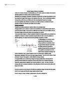
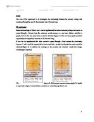
Aim The aim of this experiment is to investigate the relationship between the current, voltage and resistance through the use of a fixed resistor and a filament lamp. Hypothesis Based on knowledge of Ohm's law it can be hypothesised that when increasing voltage and current is passed through a filament lamp the resistance would increase in a non-linear fashion, such that a graph similar to the one given below would be obtained (figure 1). This non-linear graph would be expected due to temperature increases in the filament lamp. It can also be hypothesised that when current is passed through a fixed resistor the relationship between V and I would be expected to be linear such that a straight line through the origin would be obtained (figure 2). In addition the readings on the ammeter and voltmeter would both change accordingly as expected. The shape of a fixed resistor current-voltage graph (I-V graph) is explained in figure 3 since the three variables are related through Ohm's law. Circuit Diagrams Equipment Fixed resistor & Filament Lamp- to impede and obstruct current flowing through circuit Ammeter- to measure current flowing through the circuit Voltmeter- to measure the voltage present in the circuit and to make sure the power supply is correctly calibrated. Power Supply- to act as the adjustable power source for the circuit Wires- to connect the circuit

Structural Defects In Metals.
Structural Defects In Metals Metal Structure Most solid materials found in nature exist as a polycrystalline form rather than a single crystal. They are actually composed of millions of grains (small crystals) packed together to fill all space. Each individual grain has a different orientation than its neighbours. Single crystals of metals are soft and malleable, while polycrystalline metals are harder and stronger and are more useful industrially. Most polycrystalline materials can be made into large single crystals after extended heat treatment. The three main structural forms taken by metal crystals are: - * Hexagonal close-packed (HCP) * Face-centered cubic (FCC) * Body-centered cubic (BCC) The fact that different metals take different crystalline forms (and the same metals take different crystalline forms under different conditions) is evidence of "secondary bonding". Grain Boundary An important region of study is the interface between grains called the grain boundary. This is an area of random disorder typically 2-3 atom spacings thick in which a boundary between two neighbouring crystals must consist of atoms claimed by two differently orientated systems. Misfits and voids are therefore inevitable, so that the structure of grain boundaries is essentially irregular. The crystal boundary atoms thus occupy positions of higher energy than those within the body of

How can static electricity be illustrated using a Van de Graaff generator?
Tristan Allen and Erin Hankin Physics Research Paper Static Electricity How can static electricity be illustrated using a Van de Graaff generator? The objective of this experiment is to exhibit the idea of static electricity using a Van de Graaff generator. In order to effectively demonstrate the effects of static electricity using a Van de Graaff generator, it is imperative to have an understanding of information relative to the subject. In building an understanding of the material, there are 3 essential points of information that must be acquired. First, the definition of static electricity must be acknowledged. By definition, "Static electricity is electricity at rest- an accumulation of electric charge known as an electric current."1 The penultimate important aspect of this experiment that must be acknowledged is the ideas of atomic theory and the role atoms have in the phenomenon of static electricity. Lastly, it is imperative to comprehend what a Van de Graaff generator is and how it operates. Grasping a complete understanding of these 3 concepts and ideas allows the exhibition of static electricity through a Van De Graaff Generator to be done with a great deal of comfort. When obtaining information on static electricity, it is necessary to first understand the concept of atoms. Everything in the universe is composed of atoms. An atom is the smallest
The purpose of this experiment was to find the normal force and the lift curve slope by measuring the static pressure distribution around a symmetrical aerofoil.The experiment involved studying the distribution of pressure for different angles of attack
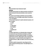
Title Pressure Distribution Around A Symmetrical Aerofoil Introduction The purpose of this experiment was to find the normal force and the lift curve slope by measuring the static pressure distribution around a symmetrical aerofoil. The experiment involved studying the distribution of pressure for different angles of attack. There were five different angles of attack in the experiment - -4, 1,6,11 and 16 degrees. To discuss about the experiment it is needed to understand some phrases. And they are as follows: a) Aerofoil b) Lift c) Angle of Attack d) Lift Coefficient e) Drag f) Stagnation point Aerofoil An aerofoil or airfoil section is a two-dimensional object, the shape of the cross-section of the wing, with the function of producing a controllable aerodynamic force by its motion through the atmosphere. To be useful this aerodynamic force must have a lifting component which is much greater than the drag component. In a powered aircraft the motion through the air is provided by the thrust so, in effect, the aerofoil is a device that converts thrust into lift. Normally the aerofoil is incorporated into a wing with upper and lower surfaces enclosing the load bearing structure. The aerofoil diagrams are in figure 2 and 3. Lift When the aircraft is cruising in straight and level flight, at low altitudes, the wings are set at a small angle, 2 to 5 degrees, to the