Ammeter:
I will need a special digital ammeter for the light bulb and thermistor, as the scale of the normal ammeter is not sensitive enough to detect the small changes in the current.
Voltmeter:
To change the voltage in order to change the current.
Three components, which are:
- Light bulb
- Thermistor
- Metal wire
I will use a variable resistor instead of the metal wire to give a constant length
of the metal wire. A short length metal wire will have a very low resistance and the wire will heat up or even melt due to the very high current. I have to make sure I don’t move the contact to keep the length of the wire constant.
There are four factors that affect resistance as I mentioned above. Now I will say how they affect resistance.
- Length:
Resistance is proportional to the length of the wire, meaning as the length of the wire increases, the resistance also increases. This is because the longer the wire, the further the electrons have to travel, so there is more chance of them colliding with metal ions. Therefore the resistance is greater.
- Cross-sectional area:
Resistance is inversely proportional to the cross-sectional area meaning as the cross-sectional area increases, resistance decreases. This is because if you increase the cross-sectional area of a wire, the electrons have more room to flow through the wire. Therefore the resistance decreases.
- Material:
Different metals have different resistances. Some metals are said to be good conductors of electricity meaning they allow electricity to flow through them easily. Therefore they have a low resistance. Some materials are called semi conductors. They conduct electricity, but they also have a high resistance. This is the variable I will be investigating.
- Temperature:
Resistance is also proportional to temperature. Therefore as temperature increases, the resistance also increases. This is because as temperature of the wire increases, the atoms have more energy to vibrate and the metal expands a little as a result. The electrons find it harder to travel through vibrating atoms and therefore the current flow decreases and the resistance increases. In some substances increasing the temperature actually lowers the resistance. This is the case with semi conductors.
Above I have said how length, cross-sectional area, material and temperature affect the resistance. As these factors affect resistance, I will have to control them except for the material of my component as that is the factor I am looking at. So my control variables are the external temperature, length of wire, thickness of the wire and also use the same apparatus in all my experiments.
However I can not use the same ammeter for all three components because the current reading of the light bulb and thermistor is not recognised by a large scale ammeter, therefore a digital ammeter is used to measure the small current in the light bulb and thermistor.
Method
- I will firstly set up my experiment for each component.
- To do this I will place a variable resistor in series with my ammeter, power pack and component. I will place a voltmeter in parallel to my component.
- I will then adjust voltage the voltage using the power supply until the voltage reads 2 volts.
- I will then record the reading on the ammeter making sure the variable resistor is set to its maximum value.
- I will then increase the voltage up to 4 volts and again record the reading on the ammeter.
- I will then repeat the experiment twice and tabulate my results and also state my average values for current and voltage.
- Once I have completed all this, I will change my component and again do the same thing as I done for my first component. This will again be repeated for my third component.
- After obtaining all my results, I will then graphically represent my results for each component.
- I will then analyse my graphs and state my interpretations of the graphs. I will then conclude by mentioning if the component is an ohmic conductor or not.
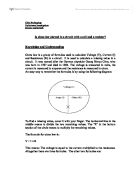
The general circuit I will be using for all three components will be set up as follows:
Safety
There are some aspects of safety whilst doing the practical that should be taken into account when carrying out this piece of work:
- I cannot exceed the voltage a lot as this may damage the light bulb and make the electrical circuit unstable.
- I should not leave the electricity running for long periods of time, as this is also dangerous as it may cause over heating in the circuit.
- When heating the circuit, make certain that the power supply is turned off.
Results
Metal wire
Thermistor
Light bulb
Conclusion/Analysis
After tabulating all the results I got for all three experiments, I drew graphs for each component. As you can see in my graphs, my graph for the metal wire has come out to be a straight line. This tells us that the gradient of the graph will also be constant as the gradient at different points on a straight line are all equal. This also makes the resistance constant. This means that as the voltage increased, the current also increased proportionally. This is what Ohms law states that voltage and current are both proportional to each other, which shows that the metal wire obeys Ohms law. This is what I predicted will happen and so my hypothesis was proved correct. The thermistor and the light bulb graphs turned out to be curves, which shows us that voltage and current do not increase proportionally in these two components, therefore they do not obey Ohms law. For a component to obey Ohms law, both have to increase at a proportional rate and therefore when plotting the results, come out to be a straight line graph, and the only straight line graph I got was of the metal wire so therefore the metal wire obeys Ohms law.
Evaluation
By doing this investigation, I have found many things. Firstly I found what voltage, current and resistance are and what effect voltage and current have on the resistance of different components. I have also found how resistance can be calculated and how three factors (voltage, current and resistance) can form a formula in relation to each other making either one the subject of the formula. I also learnt how to set up an ideal practical experiment, obtain my results, tabulate them, convert them to graphs, analyse them and interpret my graphs. I also learnt to implement safe working procedures using a variable resistor. This ensured that the component was not left on in the circuit for a long period of time.
There are also some improvements I could have made to my experiment in order for it to be even more accurate. One way I could have improved my experiment is by using a sensitive millimetre to obtain a very accurate set of results. I could have done is increasing my voltage in 1 volts in order to get more readings.