The history of Magnets and electromagnets.
Magnets and electromagnets have many uses, every electric motor, generator or transformer requires a magnetic field for it's operation. With the exception of a few special types, all use electromagnets. The magnets mounted on large cranes are used to lift heavy loads. Magnetism makes the generator supplying the electricity to your home work and the radio, telephone and most other electrical gadgets work. The properties of Magnetism were known to the Greeks as early as 700 B.C. It was found that a certain type of ore had the power to attract pieces of iron which were in it's vicinity. The discovery was made in a province called Magnesia, and the ore was given the name Magnetite after its place of discovery. The type of magnetite which exhibits magnetic properties is commonly known as Lodestone. Any material which exhibits these magnetic properties is called a Magnet. The first uses of magnetism were recorded by the Chinese, who are believed to have used suspended pieces of magnetite as compasses nearly 2000 years ago. Compasses were also used by the European navigators, but not until about 1200 A.D. Christopher Columbus was interested in the properties of magnetic compasses, and he made some important observations on the accuracy of compasses during his voyage to America in 1492. However, the first true study of magnetic properties was not attempted until 1600, when William

Measuring Young modulus of copper
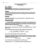
Physics TAS Full Report D1:Measuring Young modulus of copper 19-10-2006 Aim -To show that solid matter (copper wire) obeys Young modulus by finding the relationship between the load which is loaded at the end of the wire and extension of the copper wire. -To show that solid matter (copper wire) obeys Hooke's law in elastic deformation condition. Apparatus Copper wire Slotted mass with hanger (0.1kg each) G-clamp Adhesive label Wooden blocks Micrometer screw gauge Half-meter ruler Safety goggles Pulley on clamp Procedure . A micrometer screw gauge is used to measure the diameter d of the wire at 2 or 3 different points along its length and is taken the mean value. 2. The apparatus is set up on the bench as shown above. Be fixed an adhesive label on the wire as a marker. 3. Original length l of the wire from the wooden blocks to the marker is measured before be added slotted mass to the wire. 4. The wire is loaded in steps and be recorded the extension e produced. Data Analysis and Results . Measurements of the diameter of wire st measurement 2nd measurement 3rd measurement Diameter d/m 0.0003 0.0003 0.0003 Mean diameter of wire d = 0.0003m 2. Measurements of the original length of wire st measurement 2nd measurement 3rd measurement Length l/m 2.9960 2.6400 3.7730 3. Measurements of the extension of the wire with load and

Young Modulus of Copper
Young Modulus of Copper Date of experiment : 23 / 9 / 2009 By 7M Lam Kai Lok (10) _ Group 4 Objectives : To measure the Young modulus of copper by finding its elastic limit first , followed by measuring the ratio of stress to strain within this range . Apparatus : 2 copper wires , 1 G-clamp , 2 wooden blocks , 1 half-meter rule , 1 meter rule , 1 micrometer screw gauge , 1 pulley clamp , 2 adhesive label and slotted masses with hanger Theory : Recalling the memory of Hooke's Law that we learn in F.6 , it states that the extension of the spring is directly proportional to the force applied on it , which is F = kx . What's more , when we examine the fundamental nature of the spring , we can see that spring is actually a rolled wire , therefore someone suggest that the Hooke's Law can also be applied to explain the relation between the force and the extension of a wire . After a lot of experiments , physicists have found that for most metals , the results obey Hooke's Law at the beginning ; However , after reaching a certain value , the results are not consistent with what the Hooke's Law states . Afterwards , they try to explain this with the atomic model and here below is the common behavior of some pure metals : As for this experiment , we are trying to verify the above results and find the Young modulus of copper , which is its stiffness . And this is going to

Measurement of Young modulus of iron
Mok Man Hin 7B (19) D2 Measurement of Young modulus of iron Objective To find out the Young modulus of iron by adding water into the water bucker to increase the load of the iron wire held. Record the extension of the wire at difference mass of load and plot out a graph of the extension of the iron wire against the mass of the load to find out the Young modulus of the iron wire. Procedure . Measure the diameter of an iron wire at three different points along its length by a micrometer screw gauge. Take the mean value. Calculate its cross-sectional area (A). Data 1 Data 2 Data 3 Mean Diameter of iron wire / mm .15 .17 .16 .16 Cross-sectional area (A) = _____1.0568 x 10-6_m2________________________________ 3. Measure the distance between the wooden blocks and the sticker, i.e. the unstretched original length (?) of the copper wire. Unstretched original length (?) = ___2.42m_____________________________________ 4. Add 500c.c. of water as load (m) to the water bucker holding with iron wire. Measure the extension of the iron wire (e) from the ruler. 5. Repeat step 4 until the iron wire breaks. Tabulate the results. Mass of load (m) / kg 0 4 6 8 9 0 1 3 3.5 Extension (e) / m 0 0.01 0.012 0.016 0.018 0.02 0.024 0.115 0.143 6. Plot a graph of the extension (e) of the iron wire against the mass of the load (m). Find the slope of the graph.

How do you make Electro-Magnets Stronger?
How do you make Electro-Magnets Stronger? Introduction When a current passes through a circuit it creates 2 things: Heat and a magnetic field. All things electrical create a magnetic field; this field surrounds all electrical objects in a circle like way. The magnetic field then makes the circuit/object turn into an electromagnet. An Electromagnet is something that acts like a magnet when electricity passes through it. This investigation is trying to find out how to make an electromagnet stronger and more powerful. Compared to a permanent magnet, an electro-magnet has the advantage that it can be switched on and off. However it has the disadvantage that it requires power. They have many different uses. Some of which are listed below . The crane in a scrap yard 2. Hospitals: to remove metal (iron, Cobalt, Nickel or alloys with these metals in) splinters. 3. Electromagnetic relay. A relay is something which changes a current form Big to Small, or Visa Versa 4. Doors in Banks/Jewellers Variables The different variables that can affect an Electromagnets field are: * Is the wire coiled (solenoid) * Number of coils in a wire * Different voltages * Is there an magnetic substance * Tightness (density) of the coils I will look at the number of coils and different voltages Hypotheses I think that an Electromagnet will be stronger if the wire is coiled round a magnetic
What are the physical quantities that affect the value of centripetal force when a body in circular motion? What is the force exerted on the object when the object is doing a horizontal circular motion?
Physical Science Experiment Report Centripetal Force Name_____Lee Lai Shan______ Date_______29-10-2010______ Problem statement: What are the physical quantities that affect the value of centripetal force when a body in circular motion? What is the force exerted on the object when the object is doing a horizontal circular motion? Objectives: To determine the relationship between the angular velocity of a body in circular motion , the centripetal force F necessary to maintain a constant angular velocity ,the mass m of the body and the radius R of the circular path. Experimental design: i)Apparatus: Rubber bund , 1 glass tube about 15 cm long , screw nuts with hook, 1.5 m of nylon string , small paper marker, metre rule ,stop-watch ii)Description of Design: The rubber stopper that will be swinging around in a circle for this lab travels a distance equal to the circumference of a circle. Because the rubber stopper will be traveling more than once around the circle, the total distance will be equal to the number or revolutions times the circumference. The "velocity" of the stopper is calculated then as the distance divided by the time: Equation 1 Where V = Velocity, r = radius (see diagram), N = Number of revolutions counted in 60 seconds, t = 60 seconds (length of one trial). The experimental centripetal force (Fc) of the rubber stopper swinging around is
Investigating the Damping of Motion in a Simple Pendulum through Induced Eddy Currents
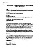
Investigating the Damping of Motion in a Simple Pendulum through Induced Eddy Currents Aim: The aim of my experiment is to determine the different permeances of several metals by measuring the effects of eddy current damping of the motion of a simple pendulum. Apparatus: The experiment involved the use of the following equipment: Electromagnet Power Supply Retort Stand w/ Boss & Clamp 3 rectangular pieces of metal, of equal volume. One of Aluminium, Copper, Titanium and Steel. A Pendulum Arm An Axle Two Small Axle Clamps, to hold the Pendulum Arm in place High Frame Rate Camera Method: To determine the effects of the induced eddy currents, I will measure the time taken for the pendulum to halve its maximum angle of deflection. I decided to use a starting angle of 30 degrees, large enough so as to minimise systematic error, but small enough that repeating the experiment wouldn't take excessively long. By connecting a video camera to a computer, I will manually raise the pendulum until the arm is in line with a line marked at 30 degrees from the vertical. I will start recording, and then release the pendulum. Using frame by frame analysis of the video I will determine the frame when the pendulum was released, and the first swing in which the pendulum achieves strictly less than 15 degrees of deflection. By working out the number of frames this takes, and dividing
Electromagnetism through a coil.
GCSE Science coursework (practical experiment) Nick Brooks 11AM Electromagnetism through a coil Electromagnetism Electromagnetic Theory In the late 18th and early 19th centuries, the theories of electricity and magnetism were investigated simultaneously. In 1819 an important discovery was made by the Danish physicist Hans Christian Oersted, who found that a magnetic needle could be deflected by an electric current flowing through a wire. This discovery, which showed a connection between electricity and magnetism, was followed up by the French scientist André Marie Ampère, who studied the forces between wires carrying electric currents, and by the French physicist Dominique François Jean Arago, who magnetized a piece of iron by placing it near a current-carrying wire. In 1831 the English scientist Michael Faraday discovered that moving a magnet near a wire induces an electric current in that wire, the inverse effect to that found by Oersted: Oersted showed that an electric current creates a magnetic field, while Faraday showed that a magnetic field can be used to create an electric current. The full unification of the theories of electricity and magnetism was achieved by the English physicist James Clerk Maxwell, who predicted the existence of electromagnetic waves and identified light as an electromagnetic phenomenon. Magnetic induction Magnetic induction is the

Electromagnets Investigation
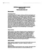
PLANNING SCIENTFIC THEORY: Electromagnets An electromagnet is a device consisting of a solenoid usually a cylindrical coil of insulated wire in which an iron core is placed. An electric current passed through the coil induces a strong magnetic field along the axis of the helix. When the iron core is placed in this field, microscopic domains that can be considered small permanent magnets in the iron align themselves in the direction of the field, thus increasing greatly the strength of the magnetic field produced by the solenoid. The magnetization of the core reaches saturation once all the domains are completely aligned, and an increase of the current in the solenoid has little further effect. When the current is switched off, the core retains only a weak residual magnetism. The Domain Theory The domain theory of magnetism suggests that a magnetic material such as iron contains within its structure tiny cells called domains and that mini molecular magnet exist inside theses domains. In an unmagnetised piece of iron all the mini magnets within a particular domain point in the same direction but in each neighbouring domain they point in different directions. The result of this is that the magnetised effect of the domains cancel each other out. In an unmagnetised piece of iron all the domains are lined up so that their magnetic effect reinforce each other. Flemming's
Gravity and Acceleration
PHYSICS LAB REPORT Gravity and Acceleration Aim: To show that the acceleration of a freely falling body is equal to the gravitational pull of the Earth. To give a comparison of the various values obtained using different methods and show how external factors play a role in the measurement of the acceleration of a body. Hypothesis: If a body is dropped from a height then its acceleration will be equal to the gravitational pull of the earth because a freely falling body is attracted towards the earth due to its gravity independent of the mass of the object and neglecting air resistance. Abstract: In this experiment the following principles will be investigated. * If an object held near the surface of the earth is released, it will fall and accelerate, or pick up speed, as it descends. This acceleration is caused by gravity, the force of attraction between the object and the earth. * Falling objects accelerate in response to the force exerted on them by Earth's gravity. Different objects accelerate at the same rate, regardless of their mass. Microsoft(r) Encarta(r) Reference Library 2003. (c) 1993-2002 Microsoft Corporation. All rights reserved. The acceleration of a freely falling body is equal for all masses but due to air resistance it varies. In this experiment the acceleration of falling bodies are calculated and compared using two different set -ups. Apparatus: