I Created a hole in the middle of a uniform meter rule and then I fitted the rotary potentiometer tightly into the hole and hold one end of the rotary potentiometer tightly with a clamp. At about 20cm – 30cm away from the middle of the uniform meter rule I attached a spring to a string hanging from the meter rule. At the other end of the meter rule, I hung masses.
HOW THE CIRCUIT WORKS:
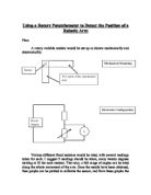
The 1k variable resistor is adjusted till the voltmeter reads 0. This is done so that when there is no mass on the meter rule the voltmeter reads zero, and when masses are added, the voltmeter reading rises from zero. When masses are added to the other end of the meter rule, the sliding contact moves upward (see circuit diagram) therefore increasing the voltage on the lower end of the variable resistor which will increase the value of my output and the reading on the multi-meter increases. The initial voltage from the voltmeter is then connected to an amplifier to make my setup more sensitive.
N.B: While I adjusted the 1k variable resistor I noticed that the value could not drop to exactly 0.00V but it gave me about 0.24V and I used this for the experiment.
PRECAUTIONS:
- When connections were not made, I ensured that the power supply was switched off.
2) When readings were not been taken I ensured that the power supply was switched off.
3) When readings were not being taken, I removed masses from the meter rule in order not to make the spring distorted.
- When I was not using the multi-meter, I turned it off in order not to run down the battery an give me an accurate result.
The electrical cell used was one of a low voltage therefore my working condition was not that dangerous.
Experiment: I Hung masses on the meter rule, then record the change in output from the multi-meter. I repeated the process two more times with different masses then found out the average of the readings for more accuracy in my result. I then used my average output to plot a graph.
Observations
In my initial experiment when masses were put on an inextensible string hanging from the meter rule I noticed that there was no change in the output reading from the digital multi-meter unless heavy masses are put and this system did not produce a sensitive setup this was when I got the idea of the Wheatstone Bridge. The Wheatstone Bridge did not give me a satisfactory result either! I then noticed that the spring was placed at the extreme end of the meter rule and that when a mass is added, the spring stretched to its maximum therefore adding more weights did not really stretch the spring significantly so the output did not really change. So I then placed the spring closer to the center of the meter rule in order to improve the sensitivity of my sensor. I observed that the values from the multi-meter were not good enough so I then connected an amplifier to my setup. This is also to increase the sensitivity of my experiment and to give me a more sensible change in output. I then used the amplified output to draw the graph.
My graph fully proves that the relationship between mass and output is proportional. It shows that as the mass increases the output increases (as mentioned in “How the circuit works”) but the model has a certain limit i.e. it can only measure weights between 0g and 100g. From the table and graph we can see that a mass of 10g cause the output to change by approximately 0.24V(amplified 10 times). Therefore for masses between 0-100g could be determined from the graph with the output produced. This does not necessarily mean that masses beyond 100g could not be measured using this model but I have decided to use 0 to 100g for convenience.
FITNESS FOR PURPOSE
Resolution:
Basically, form the table above we can see that when 1.00g is added to known masses, the output is the same for the known mass which implies that 1.00g does not make a difference to the output reading. Moreover, when 2.00g is added to known masses say 10.00g or 30.00g the output changes. Therefore, the smallest change (resolution) my setup can detect is 2.00g.
Sensitivity = Change In Output ,
Change In Input
= 0.24
10.00
= 0.024V/g
Response Time: This is the time it takes for the output to be detected by a sudden change in mass. In my model the change is almost immediate so the response time is quite fast. Although the last digit on the digital multi-meter fluctuates this only means that the change in magnitude is been resolved.
Linearity: My graph (output against mass) is a straight line graph(upward sloping) showing the relationship is proportional(as mass increases, the output increases).
Conclusion
The main aim of the experiment is to determine the relationship between mass and output and this could be easily deduced from the graph and the table. Basically this is what I expected i.e. an increase in mass would increase the output produced. From the graph we can determine the mass of object (approximately). To do this place the object on the model and read the output and read of the corresponding mass from the graph and this gives us the approximate mass.
FITNESS FOR PURPOSE
Resolution:
Basically, form the table above we can see that when 1.00g is added to known masses, the output is the same for the known mass which implies that 1.00g does not make a difference to the output reading. Moreover, when 2.00g is added to known masses say 10.00g or 30.00g the output changes. Therefore, the smallest change (resolution) my setup can detect is 2.00g.
Sensitivity = Change In Output ,
Change In Input
= 0.24
10.00
= 0.024V/g
Response Time: This is the time it takes for the output to be detected by a sudden change in mass. In my model the change is almost immediate so the response time is quite fast. Although the last digit on the digital multi-meter fluctuates this only means that the change in magnitude is been resolved.
Linearity: My graph (output against mass) is a straight line graph(upward sloping) showing the relationship is proportional(as mass increases, the output increases).