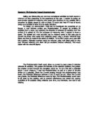
The circuit that I will be using is a potential divider circuit. A potential divider circuit is where two or more resistors in series split the voltage between them in a ratio of that to the resistance. If they both have the same resistance then the voltage will be the same across both of them (half of the total potential difference), but if one resistor has a greater resistance than the other the voltage will be greater across the one with the higher resistance.
Developing the Sensor
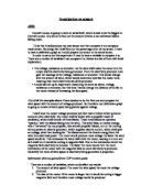
The first test that I did was with the LDR on its own passing over the grey squares. I found this to be inaccurate and the results did not follow a pattern. I wanted to have only the light reflected off the grey and not coming from an outside source, so I got some thin card and wrapped it round the LDR so that the only light going into the LDR was from the grey square. The problem with this one was that there was no light reflecting because it was too dark.
So I decided to cut some holes in the tube at the bottom so the light can reflect off of the grey. This one worked well until I tried it again about an hour later, when the Sun was behind clouds, and got totally different results.
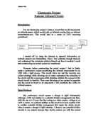
I decided that I needed a constant light source to reflect off the grey and I came up with this.
This was the final design and I found it to work well every time and I could get consistent results with it.
Plan
Apparatus
- Powerpack (5V)
- Batterypack (1.5V)
- 7 leads with connectors
- 4 Crocodile clips
- LDR
- Digital Multimeter
-
30kΩ resistor
- Bulb and Holder
- Printed page with 10 know intensities of grey.
Safety
- Powerpack plug into the mains and therefore care should be observed while using
- Powerpack must be fitted with a fuse and/or safety cut-out button
Circuit Diagram
Method
- Set up according to the circuit diagram
- Using the sensor move it onto the testing square
Results
Analysis
When I had made the sensor to be reliable and easy to use I found the experiment went very well and the result were good. The main problems were that the light kept on moving so the angle that it reflected off the paper was different I over came this by putting sellotape on the joins to reinforce it. Another problem is that it took quite along time to get all the results and because of this the bulb got darker and the voltage reading went up as a result. This is the reason why I could only get three sets of results. This would be the main problem with making the sensor commercially because as soon as the bulb started to dim the reading from the sensor would be inaccurate.
You could use my sensor on any grey and read off the voltage from the graph to see what intensity it is.
If I were to do this again I would use a white LED instead of a bulb as LED’s don’t dim and won’t stop working so they would be better to use. Also instead of using an LDR I would use a photodiode as they are more accurate and respond quicker.