This is OHM’S LAW, formulated by the German physicist Georg Ohm in the 1820s. It means that if the voltage is doubled, the current will be doubled.
The current, the voltage and the resistance of a conductor are related by the following equation:
Voltage (V) = current (A) x resistance (Ω)
Or in symbols: V = I x R or V = IR
This defines resistance. For OHMIC CONDUCTORS the resistance is constant and Ohm’s Law of proportionality holds.
The relationship above can be expressed in two other ways.
I = V/R and R = V/I
Preliminary experiments:
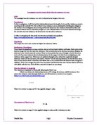
To chose which factor I am going to investigate I am going to consider how I would measure each factor and which factor would be the best and easiest to record. To measure the wire width I would use different widths of the same length and same material of wire e.g. thin, medium and thick copper wire with thin and thick nichrome wire. To record the difference in widths I would use the same voltage and measure the resistance for each thickness. Although it would be easy to obtain and record the data the graphs that I would be able to draw up would not be interesting.
For the temperature of the wire I would not be able to carry out a fair test because it is extremely difficult to produce and control the range of temperatures needed without the correct equipment.
If I chose to measure the difference in the resistance in different materials I would chose a number of different materials and using the same voltage I would record the resistance given by each wire of the same length and width. I could measure both the different material and lengths to get more results and therefore more accurate graphs.
The final factor is the length of the wire. To measure and record the findings for this factor would be simple and the results collected could show a connection between the length of the wire and the resistance given by the wire.
Using this information I have decided to measure length in 3 different types of metal. Therefore, I can simply compare which wire has the most resistance in certain lengths.
In this preliminary experiment I selected the wires that will be used in my main experiment when investing the connection between the length and material of the wire and the resistance of the wire.
To ensure a fair test whilst carrying out my preliminary experiments I was very careful when selecting my independent variable which is the width of the wire. I used a constant voltage of 3 volts and a constant width of 32 (SWG).
Apparatus:
In this experiment I used the following apparatus –
Power Pack;
Crocodile clips;
Wires;
3 Different materials – Copper, Eureka and Nichrome;
Ammeter;
Voltmeter;
Board with bare wires on;
Jockey. (A jockey is a device with a sharp edge on the end. This is used to pin-point an exact position on the wire when measuring length).
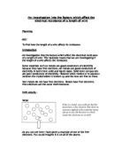
I used the ammeter and voltmeter to find the resistance using the formula:
R = V/I
Below is a circuit diagram of what the circuit looked like.
Here are the results for my preliminary readings:
Using the information I gathered in my preliminary experiments, I have decided not to change the material but keep it the same and only change the length. Due to this, I am going to add other distances into the readings; otherwise there would not be enough points to make a sufficient graph. I will therefore measure every 10cm instead of 20cm doubling to results.
Also using the results, I have decided that the 1 material that I am going to use will be Eureka because it has to highest range of results and the voltage will not get to high for the wire. I think that copper doesn’t have enough resistance and nichrome has too much resistance so the voltage is a bit too high for the wire. This would cause it to melt and make the whole experiment unfair as I would have to use a different piece.
Apparatus:
Power pack;
Ammeter;
Voltmeter;
Wire Board;
Wires;
Crocodile Clips;
Jockey;
One wire – Eureka.
Method:
Firstly, the apparatus was set up in a circuit as shown above. Then, the jockey was placed on the point end 10cm away from the end of the wire where the other crocodile clip was attached. The readings on the ammeter and voltmeter were recorded in the table on the next page. This process was repeated twice more. Then the jockey was placed 20cm away. The same was done for this distance. The same was done each 10cm along until the distance was 100cm. This was the last distance. Once all the results had been collected, the resistance was worked out.
FAIR TEST:
This experiment will be a fair test because:
I will keep the following the same:
- The material of the wire;
- The jockey;
- The amount of voltage going in.
I will vary the following:
I will measure:
- The voltage around the circuit;
- The current;
- The resistance.
Safety:
I will make sure this experiment is safe by not raising the voltage over 3V. Therefore the wire will not burn off and therefore it cannot burn me.
Prediction:
I predict that as the wire gets thinner the resistance will increase. This is because there are fewer spaces for the electrons to travel through and therefore they collide with more atoms and the wire should heat up. The ratio for this is if you have the cross-sectional area, the resistance will double. Also, as I increase the length, the resistance should increase. This is because the electrons have a longer distance to travel down the wire so they are going to have more collisions which will slow them down. The ratio for this is if you double the length, the resistance will double.
Results:
I used the Standard Wire Gauge to measure the thickness of the wires. Here are the measurements –
34 = 0.234mm
32 = 0.274mm
28 = 0.376mm
SWG - 34
SWG - 32
SWG - 28
Analysis:
I found in my experiment that the longer the wire is, the more resistance it has. Also, the thicker the wire had less resistance.
All my results followed the pattern that I thought they would. This was just that the longer my wire was, the more resistance it put up. The longer the wire got, the more voltage got through but less current got through.
From my graphs I can tell that my prediction was almost completely correct. When I doubled the cross-sectional area, the resistance almost halved. For an example, I will use a distance of 50cm, and using the wires 32 and 28 (the cross-sectional areas are shown next to the graphs). The resistance for the 32 was 4.65 Ohms while the resistance for 28 was 2.35 Ohms. 2.35 doubled equals 4.7. This is very close to being exact although the wire is not exactly double the thickness. Also, when the distance is doubled (although I don’t have any results that are exactly double) the resistance looks to be doubled. Using the results from 30cm, 50cm and 70cm I can conclude that when the length is doubled, the resistance is also doubled. These findings completely prove my original prediction.
Evaluation:
My experiment went very well, not many things went wrong if any. I think that my readings are very reliable and there are no anomalies. This makes my conclusion reliable and also helps prove my prediction. I think that my results were as accurate as I could get them. The only problem is that the voltage and current flickers so I had to take a guess at which reading to take. This could have changed some of the results but not considerably enough to change the overall reading.
I think that the procedure that I used was quite accurate. The only thing that I could say that may have made a difference was the temperature, especially for the shorter lengths of thinner wire. I would have to use complex equipment to keep the temperature the same at all times. I don’t think it would be worth it as there appears to be no massively out strange results in my table.
I think that my evidence is reliable enough to support my conclusion because everything that I said in prediction happened. This means that not many things went severely wrong (none actually). This is why my results are almost perfect.
For further work I could test different types of wire and also more thickness. I could also use more expensive equipment to change the temperature and then do that to see if it made a difference to the resistance.