Current
Current, flow of electric charge. The electric charge in a current is carried by minute particles called that orbit the nuclei of . Each electron carries a small electric charge. When a stream of electrons moves from atom to atom for example, inside a copper wire the flow of the charge they carry is called electric current. Batteries and generators are devices that produce electric current to power lights and other appliances. Electric currents also occur in nature lightning being a dramatic example.
Electric currents flow because atoms and molecules contain two types of electrical charge, positive and negative, and these opposite charges attract each other. If there is a difference in the overall charge of atoms between two points—for example, between two ends of a wire—the negatively charged electrons will flow toward the positively charged end of the wire, creating electric current. Direct current (DC) is the flow of electricity in one direction. Alternating current (AC) intermittently reverses direction because of the way it is generated.
Electric current flows easily in some substances but not at all in others. Solids, liquids, and gases that carry electric currents are called conductors. Many metals are good conductors. More than one conductor may be needed to build an —a path for electric current to move from one place to another.
The rate at which electric charge flows in a current is measured in amperes. The unit is named for French physicist , who contributed to the study of electrodynamics in the early 19th century. One ampere of electric current is equal to about 6 billion electrons per second flowing past a point.
Black body
In , a black body is an object that absorbs all that falls onto it. No radiation passes through it and none are . Despite the name, black bodies are not actually black as they radiate energy as well. The amount and type of electromagnetic radiation they give off is directly related to their temperature. Black bodies below around 700 K produce very little radiation at visible wavelengths and appear black. Black bodies above this temperature however, start to produce radiation at visible wavelengths starting at red, going through orange, yellow and white before ending up at blue as the temperature increases,.
Tungsten
Tungsten filaments have a resistivity approximately three times that of copper at room temperature. As shown in Figure 3, the resistivity increases several thousand percent as a filament is heated to incandescence. Since the temperature coefficient of resistivity for pure tungsten is relatively constant over the range of lamp temperatures, it provides a convenient means for measuring the average temperature of a filament.
Reference:
The Stefan-Boltzmann constant, symbolized by the lowercase Greek letter sigma (), is a physical constant involving radiation. A black body, also called an ideal radiator, is an object that radiates or absorbs with perfect efficiency at all electromagnetic s. The constant defines the power per unit area emitted by a black body as a function of its thermodynamic .
According to a principle of physics called Stefan's law, the relationship between emitted power per unit area (in s per square meter, denoted M) and thermodynamic temperature (in Kelvin’s, denoted T) is:
That is, the power per unit area is directly proportional to the fourth power of the thermodynamic temperature.
The value of the Stefan-Boltzmann constant is approximately 5.67 x 10⁻⁸ watt per meter squared per Kelvin to the fourth (W · m-2 · K-4).
Prediction
I predict that since the temperature of the filament lamp will prove to be some what difficult to keep constant, the resistance of the filament lamp will increase as temperature increases, therefore I will not be able to prove ohms law. Also as the voltage is increased I believe the current is increased although I do not think they are proportional to one another. Additionally I believe that the filament lamp works as a black body.
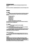
Circuit
Safety
To ensure that all students come to no harm and injuries, the basic safety procedures should be considered, such as tucking in all chairs, not in eating or drinking in class and being careful when handling equipment. The need for dry hand is somewhat important to reduce the risk of electrocution but should not touch circuit when DC supply is on, because after all we have ions in us which conducts electricity, although most material we will use is protected by plastic covering. Additionally the filament lamp will get extremely hot, and could cause burns. Large current as well as burning can also spoil sensitive equipment. Bright light emitted by the filament lamp, could cause damage to the retina if directly looked at.
Method
- Assemble all equipment essential for experiment,
- Set up the circuit as shown above, and switch off the DC supply at the start
- Check at first if the ammeter and voltmeter are working properly i.e. they are showing readings to 2 or 3 decimal places.
- Increase the voltage using the knob in the DC supply
- Increase the voltage each time by 0.1 up to 0.5, then go to 1 and from there increase voltage up to 14 volts, this would mean u would have 18 reading is the end.
- Each time you finish taking switch off power supply to cool down the filament lamp to minimise anomalies that may occur
- Record all readings clearly on to a table and work out the Resistance using the rearranged formulae; R=V/I
- Plot the values of the Current (I) against values of voltage (V) on a graph, this will then tell you the relationship, if its proportional the equation of the line will be Y=X but since this is not a perfect experiment it will not be perfect straight line.
Preliminary method
I needed to do these tests to get the hang of setting up the equipment and also checking which voltmeters and ammeters produce the best results, therefore when it comes to the real experiment I can reduce the number of anomalies and errors that can occur. In my preliminary test I used to read the potential difference off the power supply scale, by the turning the knob slowly, so it purely based on my judgement consequently it was prone to human error, however on the actual experiment I will use a voltmeter reading of voltage across the filament lamp, I will also get a digital ammeter and voltmeter where the reading are to 2 or 3 decimal places thus improving my accuracy, when it comes to calculation.
From my preliminary tests I can conclude that as you increase the voltage, the current increases as well as the resistance.
I had an anomalous reading at 14 voltages this may be due to the fact that
At extremely high voltages, the device may suffer from electric breakdown or arcing, causing a short circuit; or, at high currents, the device may overheat and melt, causing an open circuit.
Analysis
After working out the working out the resistances and plotting the graph, it showed a curve which means that voltage and current are not proportional hence does not follow ohms law, we can tell this from the graph because as the voltage increases slowly it takes up the arc shape, this was because resistance was not constant because the temperature was not constant, this meant that the two variables were proportional, because electrons have more kinetic energy, therefore increasing the collisions in the wire, although as it passes for small voltages the temperature doesn’t affect resistance as much, that’s why we see it getting less stepper as you increase voltage. We cannot making the assumption that filament lamp is ohmic because temperature was not kept at a constant.
I took logs of both the voltage and current because to see if it would show any trends, weather they are proportional or not, this is because logs bring down values and differences between values are shortened, as a result making it easier to see if there are any trends, from the graph I can confidently conclude they are proportional to each other. The other is to originate a power law to determine approximately how my inductive method faced up with the deductive side of it. I used the y- intercept and the gradient of the graph to substitute it into the following equation; I=aVb
The theoretical equation I derived was used to calculate my percentage error; I did this by taking this away from the practical one. I took the standard deviation of the difference and found the percentage error. After I decide to go a step further to work out the temperature using the following equation;
Where:
R0: The smallest resistance available in the data.
R: The resistance as we go along the data.
T: The temperature of the tungsten, due to R.
T0: The smallest temperature in the data.
α: Temperature Co-Efficient of the metal used in the lamp. I.e. Tungsten for which is 0.0044.
After calculating the temperature of each resistance I worked out power using equation; P=IV m from this I used Stephan’s law to work out values that were just the values of the temperature to the power of four. I then plotted a graph of the temperature to the power of four against the power, which gave me a linear proportional relationship. From this I can conclude filament works as a black body which is a that is a perfect radiator, and absorber of electromagnetic radiation, but does not do this at maximum intensity for all given temperatures.
Evaluation
Overall I feel as though my experiment went well. I tried my best to keep the errors to a minimum and learned vast amount from my preliminary tests which told me exactly what to expect and ways of preventing more errors. I did not get any anomalous readings. The 2.39 percentage error came due to the accuracy of my voltmeter and ammeter, this is was because it kept fluctuating and this made me sometimes guess what it reads therefore I may have made some errors. My voltmeter and ammeter were very accurate expect were only to 2 decimal places thus had an error rate of 2% a resolution of 0.02. The ammeter was more accurate because the error rate was 0.2 % and a resolution of 0.002.
I believe there was a problem at lower voltages because initially electrons with low energy need to overcome the resistance of the filament lamp, hence the current will be low.
I could not really get vast amounts of data, because of the limited voltage that the power supply went to (14V) and also due to the limited time we had which kind of pressurised me which may have caused some errors but I accept full responsibility.
Improvements I would make to the experiment:
- I would use a power supply that would exceed 14 Volts.
- I would either have a couple of filament lamps so, after every experiment I could change it so it cools down and stays at the constant of room temperature, this would mean may get even closer to the straight line graph that we expect, and prove ohms law, or could use a optical thermometer to accurately have each filament lamp at a certain temp, although we are talking about an expensive equipment and highly advanced for us.
- I could either use an exceptional voltmeter and ammeter to reduce fluctuations or an ohmic meter to see resistance and see the contrast in results we get, which would really determine if my formula is as accurate as it seems to be.
-
I could use the equation V=IR for non-ohmic devices, but it then ceases to represent Ohm's Law. In non-ohmic cases, R depends on V and is no longer a constant of proportionality but a variable called differential resistance. To check whether a given device is ohmic or not, one plots V versus I and checks that the curve is a straight line
My success was quiet high due the fact that my percentage error in the end was only 2.39% which was determined using my power law.