The resistance wire that we used is an alloy. This means that it has several different metals mixed in with the main metal. This causes problems because the mixture of metals makes it difficult for the electrons to pass through as they are passing through different atoms of metals. This slows down the current. This causes energy loss in heat as the electrons push hard to pass through the atoms.
The power pack in the circuit pushes the charge around the circuit. You could compare this to the water flowing through a pipe. The pump pushing the water round the system is similar to the battery pushing the current through the circuit. The longer the pipe the further the water has to go so the longer it takes to reach the other end.
To work out the resistance I will use this equation: V/I=R (voltage) /(current) =(resistance in Ω) to work out the resistance in the wire.
I will do a preliminary experiment to work out the different lengths of wire.
Preliminary practical
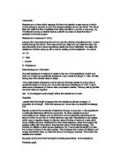
I will do a preliminary practical to define the voltage and lengths of wire to be used.
I will set up the circuit with the ammeter in place, and then I will attach the voltmeter in parallel with the resistance wire to test the volts. The circuit will look like this:
Preliminary practical Results:
Voltage
Preliminary ammeter results
The preliminary practical helps me for when I do the proper experiment. I will know what the possible flaws in the experiment are and I will know how to change the experiment so that I can get a more accurate reading.
These results show me that I don’t need to improve anything because I have no anomalous results and I didn’t have any problems during the preliminary experiment.
Plan:
I will put together the same circuit to that I used in the preliminary practical.
I will use the following equipment:
A power pack
An ammeter
A meter of resistance wire
Crocodile clips
Circuit wire
A meter ruler
A voltmeter
I will use a 4Volt power pack. One end will be permanently connected to one end of a meter length of wire. The other end will be connected via an ammeter in series to a crocodile clip, which can be connected at any point over the meter length of wire. I will attach the wire to the meter ruler so I am able to clip the crocodile clips on at different lengths. From the preliminary practical, the lengths are: 10cm, 20cm, 30cm, 40cm, 50cm, 60cm, 70cm, and 80cm.
Measurements will be taken on the ammeter when the crocodile clip is fixed at between 10cm and 80cm from the permanently connected end.
Each measurement will be taken 3 times and an average current reading calculated. I will then be able to work out the resistance using the equation V=I x R
The circuit will only be connected to the power pack for the duration of the test. The circuit will be disconnected at the end of the test.
To make this a fair test I am only going to change the length of wire, my key factor. I worked out the voltage using a voltmeter during the preliminary practical before I did my initial test. As you can see from my table, this told me that the Volts were going to change as the length of the wire changed. The key factors I didn’t change were volts, the type of wire, the circuit, and the thickness of the wire, the components and if it was insulated.
For safety reasons I wont leave the circuit on for too long, and if I use a higher voltage other than the 4 volts its in danger of smoking and will blow the circuit. When the power pack is switched off I mustn’t touch the wire because it will be hot. I will leave the wire to cool down for 15 seconds before I take the next reading.
Results
Volts / amps = resistance
V / I = R
To work out the resistance I used the equation above.
For example 0.7 V / 0.09 A = 7.7 Ω
The preliminary practical helps because when we do the proper experiment we will know what the possible flaws in the experiment are and we will know how to change the experiment so that we can get a more accurate reading.
These results show me that we don’t need to improve anything because we have no anomalous results and we didn’t have any problems in the experiment
Conclusion
My prediction was correct.
The Longer the wire was, the further the electrons had to travel, which resulted in a lower reading on the ammeter. The ammeter showed the flow of electrons passing through the resistance wire. As the wire was made longer, the further the electrons had to push to get through to the positive end of the wire and the more heat that was lost.
As the length of wire increased the calculated resistance increased. I thought that the results should have shown that an increase from 10cm to 20cm should have doubled the resistance. An increase from 10cm to 80cm should show an 8X increase in resistance. The results show that due to experimental errors they do not show this precisely. The difference in resistance between each 10cm is shown below.
I thought that each difference between each 10cm length should have been the same. The results show that there was no increase or decrease trend but the results are more random. The difference between the 50cm mark and the 60cm mark was only 0.5 ohms, whereas the difference between the 70cm and 80cm marks was 1.4. This is a variation of nearly 3X and suggests the experiment was fairly inaccurate. This shows that the resistance doesn’t go up by the same amount each time.
If the differences between each reading are averaged the result calculates to 0.95 ohms. Therefore the increase in resistance between each measurement should have been 0.95 ohms.
Evaluation
The experiment wasn’t as accurate as it could have been, however, the results do show a trend. They show that as the wire length increases the resistance increases proportionally.
The straight line drawn passes close to all the plotted points showing that the results are fairly accurate.
The results could be more accurate with the following changes:
We should allow more time for the ammeter to settle
The crocodile clip could be placed more precisely on each 10cm mark.
We could cut up the wire and clipped the wire on the ends. This would give a more accurate reading.
Looking at the graph of amps v length of wire it is possible to fit a smooth curve through the results. Also on the ohms v length of wire a straight line can be drawn between the points with very little scatter. From these two graphs I can assume that a reasonable conclusion can be drawn because the results are reasonably accurate.
To improve the accuracy of the experiment further, I could use a perfectly straight piece of wire and I could also use a pure piece of metal instead of an alloy because of the variations in the composition of alloys. I could also use better technology to measure the Resistance for example I could use a more accurate ammeter that gives a better reading to more decimal places.
I would then take several; possibly five readings, letting the wire cool down completely before reading the next result. This would make it more of a fair test, as there are a greater number of readings to take an average from. I would work out the averages and record them.
In the physics textbook by Jim Breithaupt unit B ‘resistance’ page 73 quotes in a summary that the resistance of a wire is proportional to its length.