As for setting of the mass-spring system, we used two different masses of the blocks and five different extensions per each mass, as to acquire accurate results, which are very important especially for verification experiments. For calculating k found using the air-track we used the equation for the Law of Conservation of Energy in simple harmonic motion. As the air-track is horizontal (gravitational potential energy is considered to be constant), we assume that only elastic potential energy and kinetic energy are interchanged. The Law of Conservation of Energy for simple harmonic motion can be written in the form of an equation:
In other words:
, where M – mass of block, v – linear velocity of block, k – spring constant, x – extension of spring.
Assuming the Law of Conservation of Energy to be correct, the elastic potential energy at the amplitude (kinetic energy equal to zero) should wholly change into pure kinetic energy at equilibrium (potential energy equal to zero), giving us:
, where v0 – velocity of block at equilibrium, k – spring constant, x0 – amplitude (maximum extension of spring).
Which then could be modified into:
If the value of k found using the air track system coincided with the value of k found using the weight system, then the Law of Conservation of Energy would indeed be correct, as far as springs are concerned. As our experiment is essentially composed of two distinct parts with their own set of variables, we will consider the respective parts separately in the lab report.
Variables:
Weight system:
Independent: attached mass of the weights
Dependent: extension of the spring
Controlled: spring constant k, temperature, vertical position, mass of particular weights, gravity
Air-track system:
Independent: maximum extension of the spring
Dependent: time of reaching a set distance
Controlled: set distance, spring constant k, negligible level of friction, position of the photoreceptors, mass of the air-track block
Materials:
Dynamometer, weights (accuracy 0.5 g), ruler (accuracy 0.1 cm), stable surface for the attachment of the dynamometer, air-track with photoreceptors connected to a timer (accuracy 0.01 s), block used with the air-track (with additional mass supplements – accuracy 0.5 g), string.
Methods:
Weight system:
We attached the dynamometer to a stable surface in vertical position (as long as the dynamometer is free to “hang”, gravity will position it vertically). Then we attached a weight and, using a ruler, measured the extension of the spring as shown in fig. 1 (usually dynamometers have a pointer at the end of their springs, which greatly assists the process of measuring extension as we simply check the initial position of the pointer and the new position, and the difference between them will be our extension). The same method is then conducted for additional weights. It is worth noting that one should not overdo with the weights as the spring may become permanently extended, which basically means that it is not working properly anymore and thus is trash (usually a dynamometer has written on it the maximum capacity of force that it can measure and hence withstand). As always when using springs, one must exercise caution so as no to hurt oneself with rebounding springs. Once we gathered enough data, we moved on the second part of the experiment.
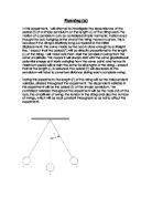
Air-track system:
Fig. 2 shows the appearance of an air-track. At point A, we attached the dynamometer in horizontal position. We took great care, so that it was positioned in one line with the rest of the air-track. Using a string with negligible weight, we then connected the dynamometer to the block used with the air-track. We adjusted the length of the string (keeping the dynamometer spring in equilibrium position), so that the block was in point B, where we both had room to extend the spring and room for the spring to return to equilibrium before passing through the photoreceptors (which were at point C). This is important as there can be no forces working on the block once it reaches the photoreceptors – the velocity with which it passes must be the maximum velocity. Once this was set, we manually pulled the block so as to extend the spring by a set length (till point D), measured the extension using a ruler (or the scale of the dynamometer when possible) and released the block. The string would contract itself when the block was released, allowing the block to move in the direction of the spring without hindrance. At point C the block would pass the photoreceptors. As the block used with the air-track is an object with set length, we were able to use a single pair of receptors, which measured the time required for the set length to pass wholly through the photoreceptors. We conducted five trials for each extension, after which we would change the extension (to other points D).
After three extensions were checked for the initial block used with the air-track, we increased the mass of the block and conducted the experiment for the same three extensions, five trials per each. Out of the results of every five trials, we have discarded the extreme one (most different from the average). It is important to keep the flow of air in the air-track at constant rate, so that friction does not have influence on results. As before, the extension of the spring cannot be too large, as it may cause the spring to brake or stop working properly. Furthermore, care has to be taken when dealing with the air-track, as a returning block may cause minor injuries. We collected the following data:
Data Collected in the experiment (gravity was taken as 10 N kg-1 and the uncertainties as given in the materials section):
Weight system:
Air-track system:
Calculation:
To calculate the spring constant we used the equations mentioned earlier in the introduction:
And
The average values of given quantities are the sums of the values of a given quantity divided by the number of values of this quantity. The uncertainties of the data collected was taken as the uncertainties of the respective instruments, while the uncertainties of the calculations were calculated as: (maximum value - minimum value)/2.
The results of our calculations:
Weight system:
Air-track system:
Evaluation:
We see that our results of the spring constant from the air-track part of the experiment oscillate around the value found using the weight-system. At some point (depending on the masses) they are even almost equal. It is interesting how k changes depending on the given extension. Why is that? There is no easy explanation. We may believe that there was, in fact, some friction on the air-track, which slowed down the block from its original velocity. This would explain the fact that the value of k became closer to our value from the first part of the experiment, as we increased extension – as the velocity was greater. Maybe the length of the string should have been chosen with greater care – it is possible that the mass-spring was not in equilibrium during the passage by the photoreceptors. And it has never been measured that the spring returns to equilibrium and not goes farther (which is very probable).
Surely, the system of extending the spring and releasing the block could have been designed better. Probably an automatic release mechanism would have been more precise. Also measuring the extension (especially in the air-track part) could have been done more precisely.
Conclusion:
Though the results may be unsatisfactory, they do show that, in fact, our method wields potential and that, ultimately, the Law of Conservation of Energy does seem to work in a mass-spring system and, if used correctly, may pose very beneficial in industry, which, in fact, it does, as the Law of Conservation of Energy is one of the basic rules behind most machines. Furthermore, our experiment shows that the air-track carries some strong uncertainty with it. In conclusion, this experiment was a moderate success.
Experiment conducted by:
Julian Barszczewski
Krzysztof Kaczmarek
Krzysztof Koć
Mariusz Long Thanh Nguyen
Lab Report written by:
Krzysztof Kaczmarek