P∞ = Static Pressure in the freestream(Pa)
U = freestream velocity (m/s)
This Equation is used to find out the coefficient of pressure with non dimensional pressure but in this experiment I am using the manometer so I can find out the pressure coefficient by using the equation:
h = the pressure at that point
ha = atmosphere pressure (tube 1)
hs = static pressure inside the wind tunnel (tube 31)
=density of air (kg/m3)
U= freestream velocity (m/s)
= density of manometer fluid (830kg/m3)
= the inclination of the manometer to the horizontal (o)
g = gravitational force (9.81 m/s2)
hs = 7.6” = 0.19304m
ha = 4.6” = 0.11684m
hs - ha = 0.0762m
R = gas constant for air ( 287kJ/kg K) (m2/s2K)
P = 102400Pa (kg/ms2)
T = Lab temperature 292(K)
=102400 (kg/ms2) / 287 (m2/s2K) * 292(K)
=1.222 (kg/m3)
(1/2)(1.22kg/m3)(U2)=(830kg/m3)(9.81m/s2)(0.0762m)(sin19.6o)
0.61V2 = 208.129
V = 18.5 m/s
It is 1.75 m/s different from the measured wind speed in the wind tunnel.
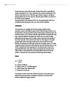
CL = lift coefficient
L = lift force
c = the chord of the aerofoil
=density of air (1.22kg/m3)
U = freestream velocity(m/s)
Experimental Arrangements
A small wind tunnel (T8) is used. An aerofoil of chord 3.5” (around 0.0899m) placed in the working section. The wind speed (V) is about 20.25m/s.The pressure across the surface of the aerofoil is measured by 14 pressure taps which are install inside the aerofoil. These tappings are connected to a multitube manometer in which to show the pressure distribution around the aerofoil. The dynamics pressure is measured by reading the different between the tunnel reference pressure (hs) and the atmosphere pressure (ha).
I set the angle of attack to -4o and then switched on the wind tunnel. It takes about 10 to 20 seconds for the fluid to become steady and then I took the result. After that I set the angle to +1o, 6o, 11o and 16o and took each reading. The manometer is inclining at 19.6o and so the fluid is not perpendicular to the markers of the manometer. The point that I took is the bottom edge of the fluid.
Result
Table 1 shows the Pressure Coefficient of each hole in different angle of attack and the percentage position of the holes alone the chord.
Fig 1 shows that when the angle of attack is negative (e.g. -4o), the low pressure area would occur under the lower surface and high pressure above it.
Fig 2 shows that when the angle is at 1o, the pressure above and under the foil are very close. The low pressure area started to build up above the surface.
Fig 3 shows that the pressure above the surface is much lower than the lower surface. In a result, a lift force would occur.
Fig 4 shows that the pressure different between the upper and lower surface. There is a huge different at x/c =0.5. The different is between -3.8 and 0.9.
Fig 5. This graph shows that when the angle of attack at 16o, the lift decreases and the drag near the trailing edge increases sharply.
Fig 6. This graph shows that the relationship between the lift coefficient and the angle of attack. When the angle of attack is over 11o, the lift coefficient decreased. The lift coefficient is negative means that the force is acting downwards when the angle is below 0.
Gradient = 200/13.75 = 14.5
Table 2.
The lift coefficient is found by counting the area enclosed by the curve of CP against x/c.
Discussion
The top part of the aerofoil generate the most lift force because in graph 3 to graph 5, it gives the biggest different between the pressure coefficient and they are located at the ratio 0.2 to 0.4 which are the holes 2 to 4.
In the lift curve graph, the angle of attack for no lift is 0o and the stall point is about 13o. At 0o, the lift curve slope cross through the x – axis, it shows that the lift coefficient is about zero. At the same time, the pressure coefficient graph shows that the pressure above and below the surface is nearly the same. This proves that at zero angle of attack the lift force is zero. However, when the angle of attack is about 16o, the pressure under the aerofoil started to decrease. At the same time, the lift curve slope at 16o is just over the maximum point and goes down.
The Reynolds number = Uc/v
U is the tunnel speed
C is the chord ( in meters)
V is the kinematic viscosity of air
= 20.25m/s * 0.0889m/1.5*10-5 m2/s
=120015.
When taking the reading from the manometer, the reading would be +.2inch. because it is inclining rather than vertical.
Conclusion
In a conclusion, the lift force occurs when the angle of attack is between 0o to 15o, this lift force is occurs due to a pressure different above and below the surface of the aerofoil. When the angle is above 15o, the lift force decreases because the flow on the upper surface breaks away from the aerofoil. At the same time the drag increases sharply. When the angle of attack increased, the air flow pattern changed and hence the high velocity above the surface and low velocity below the surface therefore it changed the pressure.
Appendix
h = pressure at point 0, 1, ,2 ,3 (tube 2- 16)
hs = static pressure (tube 31)
ha = atmosphere pressure (tube 1)
When angle of attack is -4o and at tube 5:
The Reynolds number = Uc/v
U is the tunnel speed
C is the chord ( in meters)
V is the kinematic viscosity of air
= 20.25m/s * 0.0889m/1.5*10-5 m2/s
=120015.
Density of air:
=102400 (kg/ms2) / 287 (m2/s2K) * 292(K)
=1.222 (kg/m3)
Freestream velocity :
(1/2)(1.22kg/m3)(U2)=(830kg/m3)(9.81m/s2)(0.0762m)(sin19.6o)
0.61V2 = 208.129
V = 18.5 m/s
Reference
Houghton and Carpenter, Aerodynamics for Engineering Students 4th Edition (Edward Arnold) pp. 53 – 58