Hydraulic / Pneumatic systems
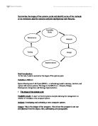
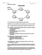
Work plan
- Produce this work plan.
- Sketch an aircraft hydraulic system that includes flaps and landing gear.
- Sketch a pneumatic emergency blow down system to be included in the hydraulic system.
- State which hydraulic fluid should be used in the system and why.
- Explain which materials should be used for the pipes and the seals.
- Describe the operation of the hydraulic system.
- Describe the operation of the pneumatic system.
- List all the safety precautions, which are to be adhered to.
Safety precautions
- Beware high pressure air can kill,
High-pressure air can reach an explosive velocity and can easily maim, blind or kill.
- When working on high pressure air systems:
- Ensure the system being worked on is isolated or the whole system is totally drained of air.
Secure any movable components.
- Never disconnect pressurised airlines.
Hydraulic fluid used, seals to be used and identification
In the system I have designed I would recommend using synthetic hydraulic fluid. Mainly because of its fire resistant properties but it also has a very good operating temperature range.
This fluid is used mainly on modern aircraft because of these reasons, which is why I have also chosen this type.
Synthetic hydraulic fluid, also known as Phosphate ester based fluid, is identified by its green, purple or amber colouring and must only be used with butyl rubber, ethylene or Teflon seals and flexible hoses.