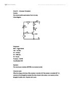
If more than 0.6V is applied to the base, the transistor switches on. Now current can pass easily from the collector to the emitter, so current can flow from the top rail, through R1, the LED and the transistor, back to the battery. The LED is now lit.
Resistance of the probes
Resistance of the probes will be referred to as RP. In dry conditions resistance RP will be extremely high, whereas in moist conditions resistance RP be relatively low.
Consider the variable resistor (VR1) and RP in series. They form what is known as a voltage divider circuit.
Operation of Voltage Divider Circuit
Consider the value of the variable resistor set so its resistance is very high.
Consider the probes in moist conditions, their resistance is very low.
With the large resistance (VR1) and resistance RD connected in series, a large voltage drop will occur across VR1, so voltage at connection of VR1 and the probes will be very small (less than 0.6V). As this is the voltage which is appearing at the base of the transistor, it is in effect switched off (the LED is unlit).
In dry conditions the resistance of RD increases, and less voltage is dropped across VR1.
The voltage at the connection of VR and the probes will increase (i.e. more than 0.6V).
This voltage applied to the base will switch on the transistor, and the LED is lit.
By adjustment of VR1, the LED can be made to switch on at a pre-determined moisture level.
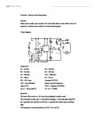
Calculation The value of R1
It is most important an LED must have no more than 2V dropped across it. Also the current flowing through should not exceed 20 mA.
When the transistor switches on the voltage at the collector is approximately 0V.
Between the top rail and the collector is 9V, so 7V must be dropped across R1.
With 7V dropped across it, and the maximum permissible current of 20 mA flowing through the LED, the size of resistor can be calculated using Ohms Law:
Note
In electronic circuits it is not good practice to have components operating at their upper limits so a resistor value of 390 or 470 ohms should be used for R1
Remember the larger the value of R1 the less current is drawn from the battery.
So the battery will last longer at the expense of the LED being a little dimmer.
Value of R2
By adjusting VR1 so its resistance is small, the voltage on the base could be very high. This high voltage could damage the transistor. It is for this reason a base resistor (R2) should always be inserted.
R3 is also placed in circuit as a safety precaution.