Potential Divider
Potential dividers are used in circuits to divide the voltage across a line in the circuit. They are generally used is circuits which require calibration or adjustments of voltage across components in the circuit. For example when a voltage of 6V is required across a circuit generally a 9V battery is needed, to achieve the 6V the only option that can be used is a potential divider.
E.g.
When two resistors are connected in series which have the same value (1k) the voltage is halved, such as if the voltage across the resistors is 9V then this shall be divided into two which shall be 4.5V.
On the other hand if there are two resistors of different values (1K and 2K) the voltage in the circuit shall be 6V when a 9V supply is used. The formula to work this voltage across the circuit is as follows…
V = Supply Voltage x R2/R1+R3
9V x 2K
1K + 2K
= 6V
Sensors
A sensor is used in a variety of circuits and can be used for a range of applications. Sensors are generally used to sense, movement, heat, light and many other things. They are used in series or parallel with a fixed resistor which has the same or similar value of resistance as the sensor the circuit required. This is known as a potential divider circuit, as it consists of two resistors one of which is variable and one which is fixed, this is to compare the resistance as the resistance of the sensor changes, this can be shown by using a voltmeter across the resistors.
Plan
Aim: to calibrate a water level sensor using the main components of a fixed sensor and variable resistor in this case a potentiometer and power supply.
My circuit must be a potential divider circuit to enable calibration of the sensor. The reason a potential divider is used is because the variable resistor requires another fixed resistor of the same or similar value to compare against when the voltage is passed through the circuit.
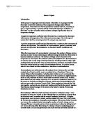
Circuit Diagram…
Potentiometer diagram...
http://sub.allaboutcircuits.com/images/05112.png
Materials
- 4x AA 1.5V Batteries + Battery Holder
- 1x Coloured 5V LED 1.5mm.
- 1x 1K Resistor.
- 1x 1K Rotary Potentiometer.
- 2x Voltmeter.
Method
To begin my practical side of my project I firstly need to measure the resistance of the resistors in my circuit by using a Ammeter and connecting it in parallel with the fixed resistor first and set the meter to 2k Ohms, it should read 0.96 or higher, it shall be lower than the provided data with the resistor due to the resistance of the wire in the resistor. Following this I shall be following the same stages that you need for measuring the resistance of the fixed resistor for the variable one (rotary potentiometer) by connecting the meter in parallel with the resistor connecting the middle and the left or right connector to the suitable ports to measure resistance.
For my circuit to work in classroom conditions I shall calibrate my sensor by connecting a LED as a indicator to view if the circuit is operating and if it is it should dim as the resistance increases on the variable resistor. Although to measure the resistance as it changes I shall connect the voltmeter in parallel to the variable resistor.
The next stage of my practical is to construct the circuit but first connecting the battery pack of the plus side to the plus side of the LED then a wire from the minus side to the fixed resistor and from there to the middle connector of the potentiometer then the furthest left connector back to the minus side of the battery. From this stage I must test the circuit by turning the potentiometer and to see the LED light intensity increase resistance decreases vice versa.
After the testing I shall connect the voltmeter in parallel to the variable resistor and begin the calibration of my sensor. I shall be creating a results table by comparing the angle of the potentiometer turn and the voltage increase or decrease. To enable me to easily measure the angle I shall stick the potentiometer to a sheet of paper which has a protractor photocopy, then connector a pointer onto the turning mechanism to allow me to read the degree of angle.
As I calibrate my sensor I shall collect result and write them in a table of results by measuring the voltage increase or decrease at each 10oc angle change of the indicator.
Prediction
For my potential divider circuit I predict that as the rotary potentiometer turns at each 10o c I think the voltage of the circuit will decrease thus the intensity of the LED in the circuit will decrease this also shows the resistance increasing as the voltage will decrease due to the higher resistance acting upon the p.d from the battery in the circuit thus a decrease in voltage.
Results Table
Chart To Compare The Voltage Against The Change Of Angle
Safety Aspects
For my experiment I considered many safety aspects. As I was using live voltage in my circuit I made sure there no lose connections or any sources of shorting and any loose conductors which could cause a failure in the circuit. I proceeded with testing the circuit after all safety aspects were considered and checked.
Also wires tend to be fray with excessive use, before using the cables I checked each cable of any danger of fray wires which could result in a cut or scratch on me.
Evaluation
My instrumentation project went according to the plan and method I had written. Also my predication that I wrote about my experiment was correct as the intensity of the light decreased as the resistance of the rotary potentiometer increased when turning it 10o c clockwise.
I feel I could have improved my project by attempting to reduce the internal resistance of the wires and semi conductors in the circuit, to resolve this the only option I would have is to change the wires to a better conductor such as Gold or Platinum, although due to being limited to the school equipment I had no choice in using standard copper wire. Also I could have increased the surface area of the components for connecting in the circuit to once again reduce any short or loose connection to enable the P.D to travel through the ions more freely.
Also in my experiment I could have made it more of a fair test by carrying out my practical experiment by repeating the experiment 3 or 5 times then finding the average from the results that I collected from calibrating of the sensor.