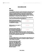
This circuit will give us both a reading
for the current and voltage across the
external load. Take readings for several
different external resistances by using
resistors, for each record the current and
voltage. Use the readings to produce a
graph and then to predict a value for
the internal resistance.
Equipment:
Zinc chloride battery
Alkali battery
Ammeter
Voltmeter
Resistor holder + resistors
Crocodile clips
Connecting wires
Battery holder
Variables and Accuracy:
In this experiment the variables that I am going to change and measure are the resistance of the external load, which will vary from 1Ω to 180Ω, the accuracy of which are 1% so the larger the resistance the less accurate the reading will be as the % error becomes more of the actual resistance, e.g.
Small resistance % error = 1 Ω*1% = 0.01 Ω
Large resistance % error = 180 Ω*1% = 1.8 Ω
By changing the resistance of the external load it also changes the current flowing through the circuit and the voltage across the external load, so I will be measuring these so I can create a graph. Other things that vary that could affect the accuracy of the readings are such things like the resistance of the ammeter, voltmeter and wires in the circuit. Also if the battery is left on for long periods of time its emf will actually decrease, so the battery should only be left connected while taking readings. If the resistors heat up this will also affect the internal resistance, so for safety reasons the current shouldn’t be made to go above 1A as the resistor will heat up and this is dangerous as it could cause a short circuit.
The accuracy of the voltmeter and ammeter are to 0.005 volts or amps, I could improve the accuracy of my results by using a multimeter, which is available for me to use, but I feel that this will give me readings that are too complicated to work with and feel that due to time I would work better with only 2d.p readings.
The variable that I will keep constant is the exact battery I use for my results, so if I have to repeat any anomalous results the battery will still have the same internal resistance.
To check the accuracy of my readings I can calculate the current and voltage using the equation V = IR. Therefore by considering the sensitivity of the equipment I can work out maximums and minimums if I need to. This may help if the readings for the current become very small and will help improve my accuracy when plotting a graph.
Results:
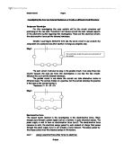
By collecting this data and using the equation V = rI – E I can plot a graph where the gradient will be the internal resistance and the y intercept will be the emf, and with these results I will be able to tell if the battery obeys Ohms law and prove if modern batteries have a high internal resistance which could lead to poor performance or not.
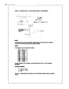
Alkali Battery:
Zinc Chloride Battery:
In the results table I have decided to record the calculated current to 3 d.p. as for the smaller measured currents it gives an idea of how the current at a given resistance would be plotted on a smaller scaled graph and on which side ( 0.005) it is from the measured current. The calculated values for voltage are not very useful when it comes to comparing them to measured voltages as the current becomes ever smaller and the inaccuracies larger. This is why I have decided not to plot a graph using calculated voltage or to show them on any of my other graphs.
With the best fit line that I have been able to draw on my graphs I am able to calculate values for the internal resistance on the two batteries. The first graph that I drew for each battery includes a result of 3.3Ω, which has a very high current and so I repeated the graph omitting this result, hoping I would get a more accurate value for the internal resistance as I used a smaller scale. The graphs I then drew gave me a more accurate result for the internal resistance, I believe that at the lower resistances that the resistors heated up affecting readings for the current and this is why they didn’t follow the trend that all my other points followed.
I compared my results to what others in the group got:
The general trend was for the internal resistance to increase in the zinc chloride battery. Using what I found out and comparing to others in the group the results show me that the internal resistance of a modern (alkali) battery is smaller than that of the other. This leads me to the conclusion that the modern batteries don’t have a higher internal resistance and that the performance of the toy car cannot be blamed on this. Internal resistance is due to the material that the battery is made from, the internal resistance of any power supply cannot be removed but it can be measured. When there is a current flowing through both r and R, energy is transferred in the internal resistance (r) of the battery as it gets warm, and also in the external load (R). This means that the terminal p.d. (the p.d. across R, the external load) is less than the full emf of the battery. So if the battery has a high internal resistance then less power is transferred to the circuit.
In this case the resistance of the external load is fixed, i.e. the toy car, and the current depends on the internal resistance of the battery. So if the battery has a high internal resistance then a smaller voltage will flow, if the toy car has a small resistance the power of the battery will be drained very quickly and this may be the problem in this case.