- The actual thermistor: Different thermistors may have different responses so the same one will be used for all readings.
- The thermometer: Different thermometers may have different responses so the same one will be used for all readings.
- The multi-meter: Different multi-meters may have different responses so the same one will be used for all readings.
- The speed the water cools at: If the water cools too fast then the thermistor may not respond fast enough. In each of the repeat experiments, the water will be assumed to cool at the same rate as room temperature will be almost the same.
Dependent Variables:
- The resistance of the thermistor: This will be followed and recorded every 5 C fall in the water temp.
Method
Apparatus
Firstly the thermistor is connected to the multi-meter.
For the next part the following shall be needed:
- A thermometer
- A kettle
- A large beaker
- Ice
- Salt
Our aim is to find the resistance, so firstly we make sure the settings on the multi-meter is set to Ohm’s, the units for resistance. Next, fill up the large beaker with boiling water, done straight from the kettle. Then place the thermometer into the boiling water. Checking the temperature is slightly over 90C, ready for the thermistor to be placed in the beaker once it’s at 90 C. When the temperature falls to 90 C, then the thermistor should then be placed into the beaker, sunken underwater. Because there is a danger with the interaction of water and electricity, it is important to either wear gloves or use a non-conducting material to hold the wires to the edge of the beaker. Letting the water temperature fall through 90 C avoids the experimental error of trying to hold the water exactly at 90 C.
Once the reading of the temperature is 90 C on the thermometer, read the resistance on the multi-meter and record it, and every other time the temperature drops by 5 C. To help us speed up the process, we can use cold water or ice to drop the temperature. The water and/or ice must be thoroughly mixed to ensure that it is all at the same temperature; otherwise the water around the thermistor will be at a different temperature, to that around the thermometer. Room temperature is at around 20-25 C, so once the water reaches around this temperature, ice and/or cold water will have to be used to drop the waters temperature. When the temperature reaches around 15 C you begin to notice the temperature drops in small amounts and we want to find results to from 90 C-5 C, so this is when you add the salt to the water. After completing the task, repeat it another two times exactly the same to the first. Now from three sets of results we can work out an average.
The thermistor
A thermistor is a semi-conductor metal oxide, which is used to sense the alterations in temperature. It does this by altering its resistance, but not in proportion to the change of temperature. When the temperature increases the resistance of the thermistor drops, but not linearly. This is due to electrons in the thermistor gaining more energy because of the temperature increase. They then gain more kinetic energy i.e. a lot of movement, due to the temperature increase. When the electrons have more energy they are then more free to move. With more movement, conduction in the thermistor is easier as the electrons that would have been in the way of the flowing current are now able to contribute to the current. So if the temperature decreases, the opposite happens and the resistance will increase.
Hypothesis
I predict, therefore that the resistance in any experiment will rise as the temperature of the water falls.
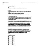
Results
These results are shown in the graph on the next page
Evaluation of my system
The results are shown in the table to one decimal place, not two from the metre. This is because the temperature can only be read to the nearest degree from the thermometer and the level of accuracy to 1/100 of an Ohm is not appropriate. The thermistor we are using has a resolution less than 5 C, and this is when we can get the best results because during this temperature, the thermistor can tell the difference between temperatures from its resistance a lot more accurately. Therefore the Thermistor was suitable for this experiment and also the range and interval of the temperatures were suitable for the experiment. The graph shows that most points lie on, or close to, the line of best fit and therefore I can conclude that the experiment worked well as the results fitted the predicted pattern.
However anomalies can be spotted in the results, for example, the first results for 35 C and 30 C do not fit with the second and third which are more alike. Further repeats way avoid this inaccuracy. Another way to improve this experiment would be to use computer data logging to follow the resistance at all times and temperature, not just every 5 C. It could also be used to follow the temperature falling as well. After this range it is unlikely that the system will get the temperature right. If the temperature were to exceed, the domestic tank would probably be of no use because the system needed to judge the temperature and respond if necessary might not be familiar with a dangerous temperature in time, or may not respond at all, causing problems to the tank.
To improve this, we would use an Amplifier, which alerts the danger much faster. A thermistors response time is usually slow, however, with the aid of an Amplifier, problems will be alerted much sooner. It works by sensing on small changes in resistance through the thermistor. The amplifier then picks up on this, then amplifying the current at a much faster speed so the circuit responds quicker. When the temperature exceeds 65 C or drops below 25 C, my circuit will recognise this and respond by passing the information to an additional circuit, which will respond by cooling or heating the water. Heating if below 25 C, or cooling if above 65 C.
My circuit would look like this. It’s a circuit from ‘Advancing Physics A1, IOP Publishing’