Find the separation between two cones of the same type on the fovea of the eye by using the resolving power of the eye.
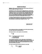
Resolving Power Of the Eye Objective: Find the separation between two cones of the same type on the fovea of the eye by using the resolving power of the eye. Introduction: The retina contains two types of light detecting cells: rods and cones. Cones provide the eye's colour sensitivity, rods, though more sensitive than cones do not detect colour. There is an area on the retina with a much higher density of cones called the fovea. When an object is observed its image is focused on the fovea. The fovea is a 0.3mm diameter area containing on rods and very thin densely packed cones. Cones can be divided into three types; one type detects each of red, green and blue light. The green and red cones are concentrated in the fovea centralis. To measure the separation between two cones in the eye we can use the resolving power of the eye, for two objects to be resolved optically the viewer must be able to clearly differentiate two distinct bodies. (Rayleigh's criterion:? = ?/d) Critical case shown where objects are just resolved For two light sources of the same wavelength to be resolved the light must stimulate two cones on either side of one unstimulated cone. Resolving power due to a circular aperture can be calculated by: ? = 1.22? d Where: ? = resolving power of optical instrument ? = Wavelength of light d = diameter of aperture The resolving power of the eye will
Finding the Focal Length of a Lens.
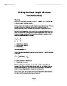
Finding the Focal Length of a Lens From Activity 23 (1) The Into Lenses have fascinated physicists ever since... well they have fascinated Mr. E. Allen so that's more than enough. Anyway, lenses can be used to modify images in a number of ways. They can be used to focus, blur, enlarge, reduce (which is still technically an enlargement with a factor less than one) and flip an image upside-down. With all of these properties, there must be some rules governing how a lens works. In physics this means there are some mathematical rules, which can be shown through equations. For lenses, there is the lens equation, which states that when the image is focused: u - Object to lens distance v - Lens to image distance ƒ - Focal length The Lens Equation (2) There is also another equation relating the focal length of a lens to the power of the lens: and thus P - Power of a lens in dioptres (D) ƒ - Focal length in metres If we know the power of a lens, we can work out the focal length and likewise, if we know the focal length we can work out the power. Once we have the focal length of a lens, we can work out the object-lens distance and/or the lens-image distance through the lens equation. There is even more. We can also work out the enlargement factor between the object and the image by drawing ray diagrams. Ray Diagrams (3) Armed with all of these techniques, we will

The purpose of this laboratory investigation is to verify the validity of the Lens Equation which states that 1/di + 1/do = 1/f.
Lab: Applying the Lens Equation Daniela Perdomo Lab Partner: Stephanie Landers Date: 21 November 2002 Place: Graded School - São Paulo, Brazil Time: 8:10 h - 9:35 h Purpose/Introduction: The purpose of this laboratory investigation is to verify the validity of the Lens Equation which states that 1/di + 1/do = 1/f, where di is the distance from the image to the lens, do is the distance from the object to the lens, and f is the focal length. Hypothesis: The laboratory investigators hypothesized that the data obtained in the procedure of this experiment would be consistent with the Lens Equation. Though different methods of obtaining focal lengths (f) will be used throughout the lab, the obtained f's should still be equal. Materials: * 2 double convex lenses * 1 candle * 1 box of matches * 1 meter stick * 1 lens holder * 1 cardholder * 1 candleholder * 1 blank card Diagram: Procedure: The first lens used in this investigation was a double convex lens, which indicates that light should converge when shone through it. The first way used to discover its focal length was by using sunlight. A cardholder, with a card in it, was placed on the meter stick and the lens holder, with the convex lens in it, placed in front of it (i.e. closer to where the sunlight was coming from). The lab investigators then moved the lens until the image on the card was focused enough

The focal length of a convex lens.
Physics Full Laboratory Report (3) Title: The focal length of a convex lens. Aim: *To learn the technique of locating real image by no-parallax method. *To study the real image formed by a convex lens. *To determine the focal length of a convex lens by graphical method. *To determine the focal length of a convex lens by conjugate foci method. Apparatus: convex lens on a holder (with focal length not greater than 15 cm) 1-meter ruler, translucent screen, plane mirror, optical pin on a cork, illuminated object (a lamp house with a letter 'F' on it) For further investigation: more convex lens of the same focal length as above. Principles: A convex lens (converging lens) is a circular glass plate convex on both surfaces. The non-uniform thickness causes bending of light towards the principle axis. In particular, a convex lens converges light from infinity parallel to the principal axis to a point, called the focus (F). Light rays from infinity not parallel to the principal axis are converged to the focal plane as shown in Fig. a. When an object in placed at the placed at the focus F of the convex lens, the emerging light would be parallel to the principal axis. If a plane mirror id placed on the other side of the lens as shown in Fig. b, the rays reflected by the plane mirror would follow the original path and the final image would occur at the same
Scanning Tunnelling Microscopy.
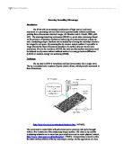
Scanning Tunnelling Microscopy Introduction The STM with its unmatched combination of high vertical and lateral resolution in a promising new tool that can be operated under ambient conditions, yielding three-dimensional detailed images, (H. Strecker and G. Persch, 1990, p441-445). The scanning tunnelling microscope (STM) is a solid-state microscope based on the principle of quantum mechanical tunnelling of electrons between a sharp tip and a conducting sample. Surfaces can be studied by allowing the individual atoms to be imaged in real space. By scanning the tip across a sample surface it is possible to image directly the three dimensional structure of a surface down to atomic scale resolutions. Prior to the invention of STM, the only way that surface structures could be deduced was by more indirect methods such as low energy electron diffraction (LEED) or medium-energy ion scattering (MEIS). Technique The tip used in STM is very sharp and ideally terminates into a single atom. The tip is mounted onto a system of piezo electric drives, which provide movement in three dimensions. (http://nanowiz.tripod.com/stmbasic/stmbasic.htm, 14/10/03). The movement is controllable with sub-atomic scale accuracy and can be brought within a few Amstroms of the conducting sample surface. The metallic tip and the conducting substrate are in very close proximity but are not in actual
Physics coursework; Finding the focal length of a lens using a graphical method.
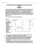
Physics coursework; Finding the focal length of a lens using a graphical method. Planning: Firstly the rough focal length of my lens will need to be found to assist me in my real experiment. A simple way to do this would be, to hold the lens up to a flat white wall opposite a window when it is light outside, by moving the lens closer/ further away from the wall until an upside down image of objects outside the window (e.g. trees,) is produced, I can estimate an focal length for the lens which provides me with the minimum distance of (u), this saves time that would be spent trying to find a point from which I can begin measurements. The equipment will be set up as shown below: Apparatus: * Light source connected to a power pack * Wire grid (object) * 1m ruler (correct to the nearest mm) * a small bi-convex lens * a white 2D screen (approx 100*70 mm) ==> When the light is turned on the light will pass through the mesh creating an image which can be focused by the lens on the screen. ==> It is important to remember that light bulbs will get hot, so precautions should be taken to ensure I am safe from burns during the experiment. ==> It should also be considered that any experiment involving electricity carries risk so due care must be taken when handling any electrical equipment. ==> The light source will be covered with a sheet of grease proof paper, this will
Lenses - experiment plan
Lenses Introduction Lenses are a transparent material shaped to refract light. Lenses are remarkable and have helped mankind develop in the so many years the world now uses for almost and visual activity from swimming goggles to open heart surgery lenses are used in some form. But lenses are not all the same. There are two main types of lenses convex and concave. These two lenses are opposites of each other and produce different images. Concave lenses are rarer to find in every day life. A concave lens is curved inwards it is shaped like two dishes placed back-to-back. Light passing through a concave lens diverges. Unlike convex lenses, which produce real images, concave lenses produce only virtual images. A virtual image is one from which light rays only appear to come from but in actual fact the do not. This appears as a smaller to produce image just in front of the actual object. Concave lenses are generally prescribed for short-sighted, people. Concave lenses help the eyes to produce a sharp image on the retina instead of in front of it. Convex lenses are more common in everyday life. The lens is very thick in the middle and thinner at the edges. With the unique shape of then lens it causes the lens to converge any light rays that pass through. This produces an image on any surface on the other side of the lens. The human eye lens is a convex lens and is more like

To investigate the relationship between u and v for a convex lens.
To investigate the relationship between u and v for a convex lens. Prediction I predict that the values of u two times greater than the focal length of the lens, the image will be diminished and the value for v will be greater than the focal length of the lens but not greater than two times the focal length of the lens. The bigger u the smaller the image and closer to the focal length v is. A simple ray diagram can prove this: I also predict that the values of v less than two times the focal length but greater than the focal length the image will be magnified and the value for v will be greater than twice the focal length. The closer to the focal length v is the more magnified the image and the bigger the value of v. This can be proved by this diagram: I also predict that for the values of u less than f a virtual image will be produced as this does not connect u and v there is no point using values of u less than the focal length. Ideal Results My Ideal results are on a separate page and were calculated using the formula /u+1/v=1/f u= the distance of the object from the lens v= the distance of the image from the lens f= the focal length of the lens I found this formula in my research (Internet, http:// relativity.phy.olemiss.edu) and is widely accepted as reliable way of finding the focal length of a lens. Preliminary Investigations My first preliminary

Microscopes.101605
The most widely used microscopes are optical microscopes, which use visible light to create a magnified image of an object. The simplest form of optical microscope is the double-convex lens with a short focal length. These lenses can magnify an object by up to 15 times. In general, however, a compound microscope is used, which has multiple lenses to provide more magnification than a single convex lens could alone. Some optical microscopes can magnify an object by 2,000 times or more. The compound microscope consists essentially of two lens systems, the objective and the ocular, mounted at opposite ends of a closed tube. The objective lens is composed of several lens elements that form an enlarged real image of the object being examined. The microscope lenses are set up so that the real image formed by the objective lies at the focal point of the ocular; the observer looking through the ocular sees an enlarged virtual image of the real image. The total magnification of the microscope is determined by the focal lengths of the two lens systems. The accessory equipment of an optical microscope includes a firm stand with a flat stage for holding the material to be examined, and some means for moving the microscope tube towards and away from the stage so that the specimen can be brought into focus. Ordinarily, specimens for microscopic examination are transparent and are viewed by

To find the best position of a lens to give the best magnification.
GCSE Physics Coursework: Lenses Experiment Aim To find the best position of a lens to give the best magnification. Theory There are two basic types of lenses, convex lenses and concave lenses. A convex lens is also called a converging lens and a concave lenis is also called a diverging lens. Convex lenses are thicker in the middle than at the edges and concave are thinner in the middle than at the edges, which is exactly the opposite. The diagram below shows some examples of both types of lenses. Diagram 1 If a beam of light is directed parallel at a convex lens then the light is brought to focus by the lens. If the beam of light is directed along the lens axis (the line through the centre of each surface), the rays are brought to a focus on the axis at the focal point of the lens. The focal length (f) of a convex lens is the distance from the lens to the point where the rays are brought to a focus. Diagram 2 If a beam of light is directed parallel at a concave lens then the light rays are made to diverge from the lens. The focal length (f) of a concave lens is the distance from the lens to the point where the rays appear to diverge from. Diagram 3 Ray diagrams are used for showing how images are formed and predicting where the image will be formed. For simplicity, rays are shown bending at the line through the middle of the lens. In reality, bending takes