- Table of results for one resistor of 10Ω
- Table of results for two resistors in series of 10Ω + 12 Ω = 22Ω
- Table of results of two resistors of 10 Ω and 12 Ω in parallel
1/Rtot. = 1/R1 + 1/R2
= 5.5Ω
- Refer to graph paper for the following Data:
The resistance can be measured by measuring the gradient of the slope, by using the following formula:
y2 - y1/x2 - x1
-
Resistance in x: y2 - y1/x2 - x1 = 4.4 - 0 / 0.36 - 0
= 12.2Ω
-
Resistance in y: y2 - y1/x2 - x1 = 4 – 0 / 0.39 – 0
= 10.3Ω
-
Resistance in z: y2 - y1/x2 - x1 = 2.2 – 0 / 0.42 – 0
= 5.2Ω
-
Resistance in a: y2 - y1/x2 - x1 = 4.4 – 0 / 0.2 – 0
= 22Ω
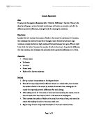
Data analysis: * Refer to graph paper
Discussion:
In the first experiment, where I tested with one resistor of 12Ω, I began with applying maximum resistance on the variable resistor. Therefore the current (I) was the least, as Resistance is inversely proportional to current. Where the ammeter read 0.18A, and the voltmeter read 2.18 volts. Then I gradually increased the resistance by pulling the handle of the variable resistor towards me, thus decreasing the resistance, and increasing both the current and the voltage. Where the ammeter read 0.20A, and the voltmeter read 2.30 volts. I continued to decrease the resistance of the variable resistor, where the current continued to increase with the decrease of resistance, associated with an increase in voltage.
In the second experiment where I tested with one resistor of 10Ω, I began by applying maximum resistance on the variable resistor, where the ammeter read 0.18A amps, and the voltmeter read 1.8v. Then I gradually decreased the resistance, thus increasing the current, which results in increasing the voltage in the circuit, because as decreasing the resistance in the circuit there are more electrons passing in a second thus increasing the current, and a large current needs a large voltage to push the electrons in the circuit.
In the third experiment, where I tested with two resistors of 10Ω, and 12Ω in series. I began like the experiments above by applying maximum resistance on the variable resistor, where the ammeter read 0.14A, and that is because the same current has to pass through two resistors, and the voltmeter read 3.10v, and that is because the power supply has to overcome to resistors to push the current instead of overcoming one resistor like the experiments before. As I decreased the resistance the current increased, thus increasing the voltage. But as I decreased the resistance the current increased at a small rate, by just increasing 0.01A, and that is because the resistance is great.
In the fourth experiment where I tested with two resistors of 10Ω, and 12Ω in a parallel connection, the resistance was small, because in a parallel connection the total resistance is less than the resistance of the separate parallel resistance. Also in a parallel connection the main current is the total sum of the current in both branches, thus the current is large and reaches up to 0.73A, where the voltmeter reads 3.85v. The large current results in a small resistance where it’s 5.5Ω, and a large voltage, because the power supply has to push a large amount of current.
Conclusion:
From the experiment I can conclude:
- In a series circuit, the same current flows through each part of the circuit
- For resistors in series the p.d is the sum of the p.d.s across the separate resistors
-
The total resistance of a series circuit is equal to the sum of the separate resistance R = R1 + R2
- In a parallel circuit the current in the main circuit is the sum of the currents in the separate branches
- For resistors in parallel the p.d across each is the same
- The combined resistance is less than either of the separate parallel resistances, because the electrons find it easier to travel when they have more than one path to take, where the total resistance is equal to:
1/R = 1/R1 + 1/R2 or R = R1 X R2/ R1 + R2
- The current through the circuit is proportional to the potential difference (voltage) across it, providing the temperature remains constant.
I V
- Resistance can be measured by:
- Dividing the potential difference across a wire, over the current through the wire.
-
Measuring the gradient of the slope, using y2 - y1/x2 - x1
- A variable resistor or rheostat is used to vary the current in a circuit. As the sliding contact moves, it varies the length of the wire in the circuit.
Evaluation:
I can say that the experiment was accurate, as the resistances calculated from the graph where equal to the actual resistance across the circuits, but there where some errors that could have been avoided in order to obtain more accurate results, and here are some of the sources of errors, and improvements: