
My aim is to produce a line follower robot with a bump sensor which can
Aim: My aim is to produce a line follower robot with a bump sensor which can reverse if it goes off course Research: Line follower robots are most commonly produced to take part in competitions. The purpose of the line follower robot is to follow a line. The robot will only follow a line that is black against a white background or a white line against a black background. This is so that the sensors can distinguish a clear difference in light and so the robot can trace and follow the line. From my research I have decided to use infrared LED emitters (phototransistors). They are fairly cheap but work relatively well. To research into the project I was going to make I looked on the internet to find other examples of the line follower robots. I found many different variations and concentrated on the components used. I looked into books and gathered information on how to assemble the circuit on the breadboard and researched on how the components work. I have researched on the type of amplifiers I could use for the line follower. I will use an amplifier to increase the current as I am using low voltage. I looked on the Maplins website (www.maplins.co.uk) and decided to use the LM386 because it is suitable for low voltage applications and it is relatively cheap. Specification: * The robot has to be able to follow straight lines, curves and turn around corners * It has to

Create a circuit that includes a sensor, which in turn will enable me to measure the volume of liquid in a container by reading the voltage from a voltmeter.
Planning Aim: The aim of this investigation is to create a circuit that includes a sensor, which in turn will enable me to measure the volume of liquid in a container by reading the voltage from a voltmeter. Plan: 1. I could use many methods to pick up a change in water level in a container. I could use a rotary potentiometer and attach it to a metal rod, then fix a cork to the metal rod, which will be used as the float that will rise with water level. I will need to use a potential divider in the circuit in order to pick up the changes in resistance, which will cause the voltage to rise or fall. 2. I could also use a length of wire, which, as it becomes immersed in water causes changes in its conductance and therefore changes in its resistance and the voltage across the circuit. I am going to use a rotary potentiometer for my investigation. [No.1] Apparatus: 6v dry cell battery pack Voltmeter Rotary Potentiometer Wires Container for water Cork Copper Rod Fixed Resistor Retort Stand Clamp & Boss Preliminary Tests: I carried out some preliminary tests with my apparatus in order to try and find the best setup for my main experiment. I tested how much water to use - because if I used under 600ml the cork wouldn't float. I examined whether to position the potentiometer so that the resistance rose when the water level rose or decreased when the water level
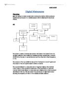
Electronics Project - Digital Metronome
Digital Metronome Planning A1: I am going to make an electronic metronome device which produces equally spaced sound at a variable speed which is displayed in beats per minute. A2: The system consists of several sub-systems. The basis of the system is the two astable oscillators. One oscillator is variable between frequencies of around 40-300 Hz by the use of a potentiometer and the other has a fixed frequency of 1Hz. The outputs of the two oscillators are put into the inputs of an AND gate and the output of the AND gate is used to drive a counter. The counter is linked to a decoder and a 7 segment display. The terminal count output of the counter is connected to the clock input of a second counter which is also linked to a decoder and a display and a third counter is also linked in this way. This sub-system thus produces a 3 digit visual output showing the frequency in Hertz of the variable astable oscillator. The output of the variable astable is also take to a series of counters and logic gates which divide the frequency of the output of the oscillator by 60 which gives an output of the same frequency in beats per minute as the frequency of the variable astable in Hertz (pulses per second). This means the display system shows the frequency of this output in beats per minute as opposed to Hertz. This output is then connected to an LED and a transistor amplifier
Experiments with Digital Systems.
Abstract: The Lab, Experiments with Digital Systems, gave us a chance to get some hands on experience with simple logic circuits, and see them work. This lab also introduced us to the Laws of Boolean Algebra. We also saw how a computer can interact with a circuit outside of the computer. Introduction: A digital system is a combination of circuits connected in some specific way to perform a specified function where all variables involved are allowed only a finite number of discrete states or values. The values that the circuit understands are in a form called binary. Binary signals consist of two numbers 0 and 1. A one represents the presence of voltage, a zero, on the other hand, represents the absence of voltage. Zeros and ones can also represent on/off, true/false, etc. The combinations of these 0's and 1's are used to represent numbers, characters, and other information. There are certain rules and theorems that make up the fundamental concepts of a binary system. These fundamental concepts are known as Boolean algebra. Boolean algebra is vital because its applications directly lead to techniques that are essential in designing efficient digital systems. An x-bit binary system is capable of 2x combinations/values. For example, an eight-bit system is capable of 28 or 256 combinations/values. However, since you begin with the number 0 we can only represent up
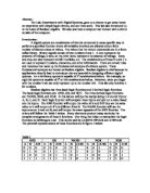
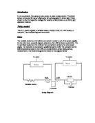
Using a Rotary Potentiometer to Detect the Position of a Robotic Arm
Using a Rotary Potentiometer to Detect the Position of a Robotic Arm Plan: A rotary variable resistor would be set up as shown mechanically and electronically: Various different fixed resistors would be tried, with several readings taken for each. I suggest 9 readings should be taken, every twenty degrees starting at 20 for each resistor. That way, a full range of angles can be tried along the whole movement of the arm. Once the results have been obtained, then graphs can be plotted to calibrate the sensor, and from these graphs the most suitable resistor can be chosen for the sensor involved. Initial experiments show that all readings will be in the range of 0 to 5 volts. Results: Voltage across sensor (V) Resistor Used in Potential Divider (ohms) Degrees 00 220 470 000 2200 4700 0000 0 0.00 0.00 0.00 0.00 0.00 0.00 0.00 20 0.35 0.17 0.08 0.04 0.02 0.01 0.00 40 3.14 2.32 .48 0.86 0.44 0.21 0.11 60 3.98 3.45 2.68 .84 .07 0.57 0.29 80 4.23 3.82 3.17 2.36 .50 0.84 0.44 00 4.42 4.10 3.60 2.87 .96 .17 0.64 20 4.46 4.22 3.78 3.13 2.24 .39 0.79 40 4.51 4.29 3.99 3.31 2.45 .59 0.92 60 4.57 4.39 4.06 3.50 2.67 .78 .05 80 4.60 4.43 4.15 3.65 2.88 .98 .22 200 4.65 4.52 4.28 3.82 3.09 2.18 .37 220 4.68 4.56 4.32 3.90 3.20 2.30 .48 240 4.71 4.60 4.38 3.99 3.31 2.42 .57

Page 2 - Specification for my nightlight.
Product Analysis What I will create a night light, where each light will come on at night and automatically switch off in the morning. Who The automatic night light will be made for the use of little children (of both genders) aged between 4-9 years old. When The child’s night light will be used whenever light is needed to brighten up a dark area, this is likely to be during night-time before a child is going to sleep or when a child wakes up during the middle of the night needing to go to the toilet. Why * For night time trips to the bathroom as there will be no need for the child to fumble around for the light switch and no longer will the child feel scared to go to the bathroom in the middle of the night. * For children who need a light to help them sleep or children who prefer to sleep with the lights on to make them feel relaxed. Where The child’s night light will be placed on a bed side table and so must be freestanding and aesthetically pleasing as the child will look at it frequently. Purpose The night light casing must fulfil the following functions: * contain and hold the electronic system * protect the electronic system from damage * make it convenient to carry, use and store the product The PCB and wires are fragile so need to be encased and protected by a hard shell. Also to prevent the child form messing with the circuit. Function To
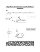
Use a sensor to make a measurement.
Introduction In my coursework, I am going to use a sensor to make a measurement. The sensor system is intended for use as a lightmeter for a photographer to detect light. I have chosen to find the respective voltages for variance of illumination on a LDR (Light dependent resistor). Things needed Two D.C. power supplies, a variable resistor, a bulb, a LDR, a 1.6 k? resistor, a voltmeter , two crocodile clips and a luxmeter. Setup The variable resistor and the bulb are connected in series to one of the power supplies. On the other hand, crocodile clips are attached to the LDR for better conductivity. The 1.6 k? fixed resistor and the LDR are then connected in series to the other power supply. The voltmeter is connected in parallel across the LDR. The luxmeter and the bulb are positioned close to the LDR on a similar level to avoid making wrong measurements. The whole arrangement is shown in the diagram below: Setup Diagram A Circuit diagram is also enclosed. Process Both the D.C. power supplies are switched on. The initial measurement of the power supplies is taken to ensure that readings by the voltmeter are sensible. In my experiment, this value was 5 V. The luxmeter is placed in parallel to the LDR on the same level so that the same amount of light from the bulb fall on both as much as possible. The voltmeter is also turned on and is set to read a maximum voltage

Test and evaluate a linear position sensor, and identify a possible use for this sensor in every day life.
Outline For my experiment, I chose to test and evaluate a linear position sensor, and identify a possible use for this sensor in every day life. The experiment was done using a variety of apparatus, as seen in the list below, and was set up as shown in the diagram which follows. Apparatus: Retort stand with two clamps 100g, 20g, and 10g weights with holder Piece of string Sensor Precautions and Safety Safety was not a big issue when doing this experiment, as no harmful materials or apparatus were used. However, some precautions were taken. I made sure that I had enough space to carry out my experiment effectively, without worrying about knocking anything over; and when applying the weights to the sensor's mechanical contact, I made sure to this gently, and not drop the weights on, which could damage the sensor. Procedure After gathering and setting up my apparatus, the circuit was connected using a pair of connecting wires, a few crocodile clips, a power source, multimeter, and of course the position sensor. In this sensor, the exact circuit set up is not known, however there are two possibilities, both of which are shown in the two diagrams which follow. Throughout the experiment, a constant supply voltage of 5 V was used, so as to maximize accuracy of the readings. The multimeter, set in voltmeter mode, was connected across or in parallel with the variable
Sensors: IR-Detector based Anemometer - Sailing and Windsurfing are common recreational activities
Sensors: IR-Detector based Anemometer Sailing and Windsurfing are common recreational activities but both require a minimum of wind depending on the experience of the user. I wanted to design an anemometer capable of measuring wind speed (and direction) in m/s, possibly with a converter to display speeds in mph or knots. It would also help if it was of sturdy design and portable to allow it to be easily relocated. To design my anemometer I first had to investigate the properties of my Sensor, a dual Infrared emitter and Phototransistor. It worked by emitting IR radiation from a diode, and detecting the intensity of reflected IR radiation from the surface it is pointed at. For the purposes of measuring wind I needed to know a speed. The easiest and most accurate way to measure speed in this case was to convert the linear wind speed into rotational speed using a simple "windmill"-type blade, and then to measure the speed of rotation. To do this I would use a cork split into quarters. Alternate quarters would be coloured using matt black paint (a very poor Infrared reflector) and silver foil (an excellent Infrared reflector). This would rotate with the windmill blades The Phototransistor itself would allow no current to pass unless it detected reflected IR radiation. The greater the intensity of the detected radiation, the greater the created current through the transistor
Buzzing In Electronics Investigation
Electronics Section A Buzzing In A1-Introduction I am going to design a system that will help me in a quiz game that I regularly play at my local youth club. The circuit will consist of a buzzer and two buttons, it may also have a light for each team. This will mean that when one of the buttons is pressed the circuit will latch and the light of that team will go on and the buzzer will make their teams individual tone. This will then be reset by one master switch. The buzzer must make a different tone for each team. A2-Analysis Of The Problem My system will need to sound a buzzer and light a light and also block out the other teams response to the question. It will also need to latch so that the buzzer and the light will stay on for a certain amount of time and then go off. This will let the whole of the system be able to work in a proper format with the brief and specification. I will use three subsystems in my circuit, a precedent bistable, a monostable multi-vibrator and an output voltage oscillator. The precedent bistable part of the circuit is the main part of the circuit, it will let one of the team's circuit latch so that they can light their light and sound their buzzer but will not let the other team do the same. The output voltage oscillator is the part of the circuit that makes the noise, the value of the capacitor can be changed so that the buzzer makes a