Making a good sensor
Making a good sensor: coursework Task: to choose, build and test a sensor circuit. The aim of my coursework is to make a thermistor component, which can be installed in a green house. The use of my system will be to regulate and maintain a constant temperature within the green house. How I aim to do this: Firstly, I would have to calibrate the values of the sensor according to temperature. This is to make sure that the system of mine would know when to open the green house window and when to close it. How the window would open? To open and close the window of the green house, the output of my circuit should be a motor. Therefore, when the output to my circuit is high, the motor will activate and as a result open the window. Making a good sensor: coursework Task: to choose, build and test a sensor circuit. The aim of my coursework is to make a thermistor component, which can be installed in a green house. The use of my system will be to regulate and maintain a constant temperature within the green house. How I aim to do this: Firstly, I would have to calibrate the values of the sensor according to temperature. This is to make sure that the system of mine would know when to open the green house window and when to close it. How the window would open? To open and close the window of the green house, the output of my circuit should be a motor. Therefore, when the
Water level sensor
As Sensor Physics Coursework Water level sensor -By Leo Contents: Aim; Planning; Circuit Equipments needed; Theory Safety; Experiment; Problem & Improvement Tables & Graphs Evaluation Aim In ordinary life, water level sensors are quite widely used. For example: An oil level sensor inside an oil tank, to measure how much oil is left in it because we cannot see it every time, and just find the level on our meters. Also a boiler works on the similar principle, the water in the boiler is quite hot and if we want to see how much the water is, we will be hurt by the vapour. We need the meter for it too. Because water level sensors are very important and there is no alternative for it, I prefer to investigate water level sensors as my coursework. Planning My main equipment is the fixed resistor and uses a float to connect with it using potential divider. While the water level changes, the resistance changes as can be shown on the change of the voltage because the ohm's law: V=IR. For my circuit, when the resistance changes by the level of water, the voltage changes with direct proportional to resistance. As the water level increased, the Resistance of water level sensor Increase as well. So the voltage share will be change. using R=R1+R2 What is potential divider? The potential divider circuit is the voltage split up between the
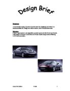
A commercial company requires a dynamic advert for displaying their wares in a showroom/office etc. Design and make an advert, which includes electronics.
Situation: A commercial company requires a dynamic advert for displaying their wares in a showroom/office etc. Design and make an advert, which includes electronics. Solution: I have a huge interest in cars especially up market sports cars like Ferrari and Porsche. I will design a 3D advert to advertise one of these models using a series of flashing L.E.D's and a car alarm. The Internet I can use the internet as the basis of my project. I can find out about different types off adverts and research Porsche. I can use it to contact different companies. Companies I can E-mail these companies for information on their products and how best to advertise them. Magazines I can use these to look for advert ideas for products. My Teacher My teacher can give me ideas on how to go about producing my project. Classmates I can survey my classmates on how they think best to advertise a car. I used many forms of information, which I have listed below and I would like to thank them for their cooperation. www.porsche.com Isaac Agnew Limited (A Porsche Dealer in Belfast) Below is a copy of the E-mail I sent to Isaac Agnew. Dear sir/Madame, I am currently studying GCSE Design and Technology at St. Louis Grammar School Ballymena and I would be most grateful if you could forward to me any information, which may be of use to me. My design brief is: A commercial company requires
555 Timer Practical.
555 Timer Practical Scenario: A chef requires an egg timer which sounds a buzzer. The buzzer needs to have an adjustable timer, so that different times can be set for the egg to boil. Method: To make an egg timer I will need to make a 555 timer with a variable resistor to adjust the time set for the egg to boil In order to do this experiment, I will need the following components to make the timer: > 9 volt battery > Battery Snap > Switch (s.p.s.t) > 2x 10k? Resistor > 0.1?F Capacitor > 1m? Potentiometer > 220?F Capacitor > 680? Resistor > Light Emitting Diode > Buzzer > PCB Board (Printed Circuit Board) > Connector Wires � Red and Black > 555 Timer + Holder The tools I will require while making the timer are a soldering iron and solder, a mini-pillar drill, and a sucker while making the Timer. I will also need 2 different sized drill-bits according to the size of the holes that I need to drill for the components to fit in. After I have collected my components, I will follow the following procedure: Making the PCB Board I will firstly remove the protective covering from the PCB Board. I
I decided to look at an electronic dice. After looking at the option I chose this electronic dice because it sounded like it could be fairly advanced.
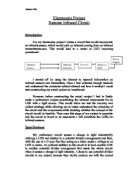
Dave George Electronics Coursework Aim We have been told for our As-level coursework, we have to design and make a circuit and were given a few ideas. I decided to look at an electronic dice. After looking at the option I chose this electronic dice because it sounded like it could be fairly advanced. This dice is to be used in board games such as 'monopoly', 'cluedo', 'ludo' and 'snakes and ladders' It has to be easy to use and cheap to build. Research For the research section I started looking on the Internet, using search engines and found very little of what I wanted. I used the 'Yahoo UK and Ireland' search engine and searched for 'electronic dice' and 'electronic dice circuits'. This showed up very little of what I wanted. It can up with results for companies that sell electronic dice kits for you to build at home rather than circuit diagrams. I then searched for 'electronic dice circuit diagrams and found... After doing this I decided to go to the library and look in books there and from home. If searched in books including, 'electronic options by P.Gormley, L.S.Hagan and C.C. Atkinson. This had no information on any relevant circuit diagrams but had lots to do with thyristors and relay diagrams. Next I searched on crocodile physics V1.7 for any relevant ideas and found what I was looking for. I found an electronic dice circuit (below) and an electronic counter

Design a make a product which is a warning device, which would be attached to my bag so that drivers of vehicles would be aware of my presence. The device should be safe to use and manufacture.
Glenn Taylor Technology Folder My Name is Glenn Taylor and for 60% of my overall Technology GCSE final mark I have to identify a problem and design a solution. The solution will be designed and built by me. This will include researching, using different techniques of manufacturing and generating ideas. Problem 1 Shed Alarm We have a shed in my garden and it is not protected very well. It contains my computer and various other items of importance and value. Although my family has thought of buying an alarm because of some recent neighbourhood break-ins, they have not found one to satisfaction. Problem analysis * Safety is of the importance so it should be safe to manufacture and safe to use * It should not harm the criminal in any way, only scare them away * It should be easy to use * Overall the main aim for the alarm is to secure the shed Problem 2 Door Bell My father works from home and as the shed acts like his office he cannot hear if people knock on the front door. This causes a problem when it is any member of my family trying to get in or when anybody needs either my father or me. Problem Analysis Problem 2 * It should be safe to manufacture and safe for the user * The bell should do as required and alert whoever is in the shed * It should be user friendly and not look an eyesore on the door. * It should be relatively easy to manufacture Problem 3

Building a mass balance to measure small weights (0g-100g) using a rotary potentiometer
BUIDING A MASS BALANCE TO MEASURE SMALL WEIGHTS(0g-100g) USING A ROTARY POTENTIOMETER Introduction: Nowadays, we have mass balances, weighing scales etc to measure masses but we hardly have devices that measure small masses. Sometimes, we may have to measure objects with small masses say 10g to 100g and my model is created backed up with this idea. Components Used: Digital multi-meter, Meter rule, Retort Stand, Clamp, Rotary potentiometer, Power supply (5V), Spring, Masses (in unit of 10g), 2k and 3k resistors, 1k variable resistor, amplifier. Reason For Choice Of Components: * Rotary Potentiometer: I used a rotary potentiometer so that when masses are placed on the meter rule the change in voltage (output) could be noted. The rotary potentiometer is of 5k Ohms but I connected it to a 5V power supply as a more convenient way of measure. As the potentiometer moves the resistance changes and also does the voltage. * 2k, 3k Fixed Resistor and 1k Variable Resistor: I used these resistors in order to make a Wheatstone Bridge so that there will be a significant change in output when masses are added to the meter rule. * Amplifier: I am using the amplifier in order to make my model more sensitive and obtain a more accurate result. * Spring: Without the spring, when masses a put on the meter rule, the masses will pull the rule till the masses came to rest on a flat
Electronic Dice Project.
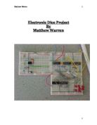
Electronic Dice Project By Matthew Warren Content Outline: Page 3 Time Scale: Page 3 Stage 1 Clock: Page 4 Switch: Page 7 Stage 2 Counter: Page 8 Stage 3 Logic gates: Page 12 Time Graph: Page 14 Stage 4 LED Display: Page 16 Final Testing: Page 16 Evaluation: Page 19 Pin Layouts: Page 21 Electronic dice 1-6 I have a problem that every time that I get out a board game the dice is always missing so what I am going to be designing and making an electronic dice that will do the range of 1 to 6,. This dice will be able to be used in most boards that need a 6 sided dice and it will be bigger than a normal dice so that it will be not as easy to lose this is a block diagram showing the process of my dice: Time Scale Stage Content Date (1) Clock Designing a fast clock 2/0103 Testing on Crocodile Clips 25/01/03 Making on Bread Board 0/02/03 Testing Clock 29/02/03 (2) 3-Bit Binary Counter Designing Binary counter 2/03/03 Tested on Crocodile Clips 0/03/03 Making on bread board 8/03/03 Testing and trying to make it work 01/05/03 - 05/05/03 (3) Logic gates Designed logic system to make only 1-6 show up 27/03/03 Tested on Crocodile Clips /04/03 Made on bread board 2/04/03 (4) LED's Designed LED layout 20/04/03 Made on Crocodile Clips Full Testing Put all stages together to test 09/05/03 Stage 1 : Clock source 555 timer The 555 will
Electronics Project - Remote Infrared Circuit.
Electronics Project Remote Infrared Circuit Introduction For my electronics project I chose a circuit that would incorporate an infrared sensor, which would pick up infrared coming from an infrared transmitter/source. This would lead to a motor or LED becoming operational. I started off by using the Internet to research information on infrared sensors and transmitters. Once I had collected enough research and understood the principles behind infrared and how it worked I could start constructing my actual project on breadboard. However before constructing the actual project I had to firstly make a preliminary project substituting the infrared components for an LDR with a light source. This would allow me test the circuitry and collect readings while allowing me to better understand the principles of the circuit and the components while deciding whether the concept of the circuit would be feasible. Then once this stage of my project is complete and the circuit is found to be reasonable I will substitute the LDRs for infrared sensors. Specifications My preliminary circuit senses a change in light intensity(By utilizing a LDR and resistor in a potential divider arrangement) and then, with the use of a D type flip-flop acting as a latch, sends a voltage to an LED or motor. An optional addition to the circuit is to have another LDR in another potential divider arrangement
Linear position sensor and Mass.
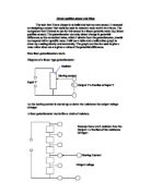
Linear position sensor and Mass The task that I have chosen is to build and test my own sensor. I reasoned on designing a sensor that could be used to measure mass and in turn force. The component that I intend to use for this sensor is a linear potentiometer (i.e. linear position sensor). The potentiometer can only detect change in potential difference so the numerical value, which I obtain from the potentiometer, should correspond with a specific mass. I will use a table and a calibration graph to show my reading clearly and accurately. The graph can then be used to give a mass value when we are given a value of the potential difference. How liner potentiometers work. Diagram of a linear type potentiometer: Resistor Moving contact Input V V Output V a fraction of input V As the moving contact is moved up or down the resistance the output voltage changes A liner potentiometer works like a chain of resistors. Because there are 5 resistors then the Output = a fraction of the resistance Of input Moving Contact Output voltage For instance, say if the voltage input was 10v and there were 5 resistors and the moving contact was on the 3rd resistor up from the bottom The voltage output = 3/5 of 10v = 6v I predict that with this principle, the mass acting upon the sensor will move the moving contact therefore changing the output voltage, which then will be