Can A Thermistor Be Used As A Thermometer?
Can A Thermistor Be Used As A Thermometer? Aim A thermistor is a type of resistor that changes according to its temperature, using this information we are going to try and find out whether a thermistor can be used as a thermometer. We believe this will happen as the resistance of a thermistor changes depending on its temperature. Method The variable we will be changing is the water temperature this will change the temperature of the thermistor which in turn will change the amount of resistance the thermistor presents.And all other variables, such as amount of batteries, will be kept the same. Our method, based on our research, is as follows: . Set up the equipment as shown in the below diagram; 2. We will heat the water to 100?Celsius 3. Take the Voltmeter reading 4. Take the Ammeter reading 5. Then we will divide the Voltmeter reading by the Ammeter reading and this shall give us the resistance. 6. We will do this every time the temperature drops by 10?Celsius and record our findings in a table, which will later be used to plot a graph. 7. When the temperature reaches the room temperature (22?) we will put ice in to the water until it reaches 0? 8. Then repeat steps 3, 4, 5 and 6 but instead of when the temp drops 10?C we will take the temp every 10?C it rises Safety Issues We will have to keep safe when handling hot water so we are going to reduce the risk
To determine e/m of an electron experimentally
Tare-sang Nam Physics 102 11/26/02 Physics Lab Determination of e/m of an Electron . Purpose To determine e/m of an electron experimentally 2. Procedure Prepare an electron-accelerator. Place it between Helmholts Coils, which produces a uniform magnetic field. The electron-accelerator creates a potential difference, v, which speeds up a negatively charged electron to . This moving charge experiences a force while it is traveling through a magnetic field; especially, when it travels through a uniform magnetic field with its velocity vector perpendicular to the field, the moving electrons experience centripetal force. It causes the circular motion of the moving electrons. Observe this phenomenon, and record the voltage applied to the accelerator and the radius of the circle along which these electrons are moving. 3. Data R (m) R2 (m2) V (volt) 0.050 0.0025 21 0.055 0.0030 39 0.059 0.0034 61 0.062 0.0039 82 0.057 0.0032 50 0.053 0.0028 29 0.060 0.0036 70 4. Mathematical Formulas and Equations where v = the voltage that accelerates electrons a = the radius of the coils N = the number of turns on each coil µ = 4?*10-7 I = the current through the coils R = the radius of the circle inside the tube 5. Graph 6. Calculations I. Given the formula, II. Using the
An experiment to see how the voltage passed around an electromagnet effects it.
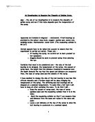
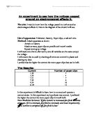
An experiment to see how the voltage passed around an electromagnet effects it. The aim: I want to know how the voltage passed in a coil around an electromagnet effects it. Here is the diagram of the circuit I will use: List of apparatus: Voltmeter, Battery, Paper clips, a nail and wire. Method: Attach apparatus as shown Switch on battery Attach as many paper clips as possible and record results Repeat turning up voltage I will make sure this is a fair test by sure all variables are the same except the voltage. I will ensure this is a safe by checking all wires are covered in plastic and clearing my desk. I predict that the higher the current the more paper clips that can be held. The Results: Current Number of paper clips .39 3.29 4.41 7.39 9.29 1.59 2 4 7 8 0 1 In this experiment it difficult to learn how to connect and operate a current meter. In this experiment my hypothesis was correct. I predicted the higher the current the more paper clips it would hold. New Modular Science: 'If the current is increased the field becomes stronger, if it is reversed, the field is reversed; and most importantly, if the current is switched off, the field is lost' From this I can conclude that the results of the experiment I have done are correct and in the bounds of the laws of nature. However some of my results (the results for 7 and 11 volts) seem to fit
What are Diodes?
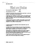
The Symbol for a basic diode is: The Symbol for an LED is: A diode is an electronic device that permits current flow in only one direction. Most diodes are semiconductors. A diode has a low resistance to electric current in one direction and a high resistance to it in the reverse direction. This makes a diode useful as a rectifier, which can convert alternating current (AC) into direct current (DC). A diode using this property is called a Zener diode. It can be used to regulate the voltage in a circuit. Semiconductor diodes can be designed to have different characteristics. A varactor diode has a capacitance that is dependent upon the voltage across it. In another kind, the tunnel diode, the current through the device decreases as the voltage is increased within a certain range. This is called negative resistance and it is useful as an amplifier. Light-sensitive or photosensitive diodes can be used to measure illumination as the voltage drop across them depends on the amount of light that they are exposed to. These are similar but not the same as LDR's (light dependant resistors). A light-emitting diode produces light as current passes through it. Some LED's can act as the light source of lasers. A perfect diode would be able to take any voltage but in the diodes we have today, when the voltage applied in the reverse direction exceeds a certain value, a

Electromagnetic Induction
AIM To determine some conditions under which a magnetic effect will produce an electric effect; and to study the factors which affect the induction of a current in a conductor. BACKGROUND INFORMATION Experiments with magnetic fields show that an electric current in a wire has a magnetic field associated with it. If an electric effect can produce a magnetic effect, maybe the reverse may also be true, i.e. a magnetic effect may produce an electric current. APPARATUS * Ballistic galvanometer * Horseshoe magnet * Bar magnets * Leads * Wired metal rod * Induction coils * 60 microamp galvanometer METHOD . The coil was connected to a Microammeter. The N pole of the magnet was inserted into the solenoid and a description was recorded. 2. The magnet was held stationary in the solenoid. A description of the results was recorded. 3. The N pole was withdrawn from the solenoid and a description was recorded. 4. Steps 1-3 were repeated with different speeds. 5. Steps 1-4 were repeated with a magnet of a different strength. 6. All observations were recorded. RESULTS Motion of magnet Galvanometer needle North pole in Remained at zero Stationary Momentarily moved to right hand side North pole out Momentarily moved to left hand side North pole in Magnitude of induced current (microamperes) Stationary 0 Slow 0.2 Fast 0.6 Strength of magnet Magnitude of

The Passage - P83 Fathers and Sons, Ivan Turgenev
The Passage (P83 Fathers and Sons, Ivan Turgenev) The country through which they were driving was not in the least picturesque. Field after field stretched away to the horizon, now sloping gently up, now dropping down again. Here and there was a copse, and winding ravines sparsely planted with low bushes, reminding one of the way in which the old maps showed them in the time of Catherine. There were little streams, too, with hollow banks and diminutive ponds with narrow dams, hamlets with squat little huts beneath blackened and often half collapsing roofs, and crooked threshing barns with wattled walls and gaping doorways opening on to abandoned threshing floors, and churches, some brick-built with the stucco peeling off in patches, others of wood with crosses awry and churchyards that had gone to wrack and ruin slowly Arkydy's heart sank. As though to complete the pattern the peasants whom they met on the way were all in rags and mounted on the sorriest little nags; willows with broken branches and bark hanging in strips stood like tattered beggars on the roadside; emaciated and shaggy crows, gaunt with hunger, were greedily tearing up the grass along the ditches. They looked as if they had just been snatched from the murderous talons of some terrifying monster; and the pitiful fight of the sickly cattle in the setting of that lovely spring day conjured up like a white

Newton's Three Laws of Motion
Newton's Three Laws of Motion Isaac Newton was born on Christmas day in 1642, in Lincolnshire, England. Newton attended Trinity College in 1661 and had both his Bachelor of Arts and his Master of Arts by 1669. That same year he became the associate of the French Academy of Sciences. He was elected to Parliament, and then appointed a warden, and finally, President of the Royal Society. Newton was a Master of Science and mathematics. He discovered calculus, before Leibniz' became popular. Perhaps Newton's most popular discovery, though, was gravity. As the story goes, Sir Isaac Newton was resting under a tree one day in his garden, when an apple fell from it and hit him on the head. Thus, he discovered gravity. The earth's gravitational pull pulls objects toward it. However, many people believe that this is only a myth created to simply illustrate Newton's discovery. Along with Newton's many discoveries, the three laws of motion are famous. These include inertia, acceleration, and the idea that for every action, there is an equal and opposite reaction. Inertia is the idea that a body in motion will remain in motion, and a body at rest will remain at rest. For example, if I were to throw a baseball into the air, it would keep going until gravity pulled it back down to earth. However, if I left it sitting on a table, it would lie there until some kind of force were to move it.

Investigation into how Temperature affectsthe Resistance.
Investigation into how Temperature affects the Resistance. Equipment: Ammeter power pack crocodile clips Measuring cylinder, ice and water Bunsen burner, tripod and gauze Voltmeter Thermometer -Set up a standard circuit, with an ammeter measuring current in amps and a voltmeter measuring voltage in volts. -place the crocodile clips in beakers of varying temperatures (using ice, water and bunsen burners to achieve them), ranging from 0 ºC to 80ºC. -Record the current in amps and voltage in volts, and repeat for each temperature. - Calculate the resistance in ?s (Ohm's) by employing the formula R = V/I (resistance = voltage divided by current) Our results indicate, on the whole, that as the temperature increases, so does the current in amps (directly proportional). As the current increases, the resistance decreases, because we are dividing the voltage by a larger number. We can conclude that as the temperature increases, the resistance decreases (inversely proportional) although there is one anomaly in the temperature of 5 ºC. We put this down to simple measuring and recording errors. Also, the voltage was not constant, in an ordinary resistor the resistance increases as the voltage increase. This is because as the potential difference across it increase, the friction of the moving particles heats up the particles in the resistor causing them to vibrate more.

Measuring Internal Resistance
Measuring Internal Resistance I am going to do an experiment to measure the internal resistance of different power sources. The different sources I am going to measure the internal resistance of are dry cells, a solar panel, a car battery and a power pack. The apparatus I am going to use are a voltmeter, an ammeter, a variable resistor, power source and a floodlight to power the solar cell. My circuit is going to be set up as follows: The experiment has no dangers except for when I am going to test the car battery because the power it supplies might be too much and cause a fire. To avoid this happening I am going to keep the resistance quite high. To improve accuracy with the dry cell I am going to use 4 dry cells and take the average, also with all the sources I am going to try and get a wide range of results at least 7 measurements for each. I am going to record my results in a spreadsheet and then create graphs showing voltage against current using this data. When creating graphs for my results, I am going to include error bars where the error margin will be 5% so that slight errors in reading my results and accuracy in the equipment are accounted for. I will then draw a best-fit line so that I can work out the internal resistance by calculating the gradient. The gradient shows me the internal resistance because: Lost p.d./current = internal resistance I have

Investagate the strength of an electromagnet
Aim The aim of the experiment is to investagate the strength of an electromagnet Introduction An electromagnet is a coil of wire wound on a soft iron core. Unlike refrigerator or bar magnets, electromagnets use electricity to generate a magnetic field. In addition, electromagnets give us the ability to turn the magnetic field on or off as we need. To make an electromagnet, you need electricity (usually supplied by a battery or a larger power source) and something for that electricity to flow through (wire coils, for example). Sometimes, the wire of an electromagnet is wound around a metal rod to increase the magnetic field strength. The electromagnet was discovered in 1820 by a man named Oersted.He accidentally discovered that a wire with electricity running though it made a compass deflect from the Earth's North Pole. In fact, the compass needle was perpendicular to the direction of the electric flow. That meant that the electricity flowing in the wire generated its own magnetic field that was disrupting the nearby compass! Since then, scientists have found many ways to use electricity to generate magnetic fields and for magnets to make electricity. Oersted observed what we now call the "right-hand rule." The right-hand rule states that if you make a fist, when you point your right-hand thumb in the direction of electric flow, the rest of your fingers curl in the direction