Investigate and construct a sensor.
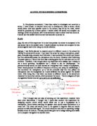
AS LEVEL PHYSICS SENSING COURSEWORK In this physics coursework, I have been asked to investigate and construct a sensor. I have chosen to examine sound and to develop and make a sensor, which would detect how loud specific rooms in the school, may be by the noise, which would be produced by a stereo system. I would create this sensor and compare my readings, which are produced, with the actual sensor used to detect how loud sound is. I would use this decibel meter and see how accurate my sensor is. PLAN: Aim: My aim of this experiment is to see how precise my sensor is compared to the real sensor that is the decibel meter. I would evaluate my sensor and compare the two sensors against each other using my results obtained. Method: I had firstly planned to measure sound in different rooms in the school, by making the actual sound sensor. I had made this sensor by using a microphone, power pack, crocodile clips, ammeter and Voltmeter. I had connected this circuit up in series and then additionally added the microphone into the circuit. However when switching the power pack on, I found that there was a reading given by the voltmeter and not the ammeter. Therefore, I had thought about my experiment and realised that I needed to use a sound generator, loudspeaker and I needed to use the Oscilloscope. The previous attempt would not have worked as I recognized that I needed a
Vacuum Chamber Investigation
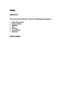
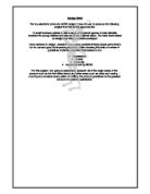
Planning: Apparatus List: When conducting the experiment I will need the following pieces of apparatus: * Rotary Vacuum Pump * Vacuum Chamber * Manometer * Valve * Short Pipe * Long, thin pipe * Stop Clock Apparatus Diagram: Safety Considerations: It is important that when setting up and carrying out the experiment no objects are poked into the belt drive mechanism of the rotary pump. The mains voltage in the mains powered equipment is also dangerous but is screened in normal use. Obeying these two safety points will help prevent physical injury and electric shock. Variables which could affect the Experiment: * The length and diameter of the pipe connecting the vacuum chamber to the vacuum pump. * The size of the vacuum chamber. * Changes in atmospheric pressure may affect the experiment. This is perhaps one of the more major variables because it can account for up to plus or minus 50 mbar. * The consistency of the Rotary Pump may be a major variable in this experiment. It is unlikely that its performance will remain constant when evacuating the vacuum chamber. This is because of heat build up in both electrical and mechanical components such as the mains transformer and seals when pumping takes place. * Changes in room temperature may cause variable characteristics in the experiment. Changes in temperature may affect several items such as the efficiency of
Linear position sensor and Mass.
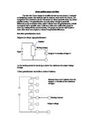
Linear position sensor and Mass The task that I have chosen is to build and test my own sensor. I reasoned on designing a sensor that could be used to measure mass and in turn force. The component that I intend to use for this sensor is a linear potentiometer (i.e. linear position sensor). The potentiometer can only detect change in potential difference so the numerical value, which I obtain from the potentiometer, should correspond with a specific mass. I will use a table and a calibration graph to show my reading clearly and accurately. The graph can then be used to give a mass value when we are given a value of the potential difference. How liner potentiometers work. Diagram of a linear type potentiometer: Resistor Moving contact Input V V Output V a fraction of input V As the moving contact is moved up or down the resistance the output voltage changes A liner potentiometer works like a chain of resistors. Because there are 5 resistors then the Output = a fraction of the resistance Of input Moving Contact Output voltage For instance, say if the voltage input was 10v and there were 5 resistors and the moving contact was on the 3rd resistor up from the bottom The voltage output = 3/5 of 10v = 6v I predict that with this principle, the mass acting upon the sensor will move the moving contact therefore changing the output voltage, which then will be
'A small business wishes to sell a range of electronic games to help alleviate boredom for young children and also be of educational value. You have been asked to design and make a suitable prototype'.
Design Brief For my electronic products GCSE project I have chosen to produce the following project from the NEAB approved list. 'A small business wishes to sell a range of electronic games to help alleviate boredom for young children and also be of educational value. You have been asked to design and make a suitable prototype' I have decided to design, research and make a portable infrared target game that is fun to use and good for improving reactions. After choosing this idea a number of guidelines instantly presented themselves to me: > Appearance > Safety > Expense > Guidelines set by NEAB For this project I am going to extensively research all of the major areas of the product such as the four listed above and other areas such as chips and casing. I must try and consider every option of fulfilling the product guidelines to the greatest amount of customer satisfaction. Design Specification This section is going to cover the rough spec of the product I am going to produce. I have compiled a list of points to do this: > The final product must cost less than £10 > The final product must be aesthetically pleasing > The laser emitter must be cased ergonomically > The product must be enjoyable for children > The product must have an ON/OFF switch > The product must have a battery power indicator LED > Mains electricity cannot be used > Battery must be

For my sensing project I decided to make a Digital Micrometer.
PHYSICS Advanced Subsidiary GCE UNIT 2862 - (a) Instrumentation Task Aim: For my sensing project I decided to make a Digital Micrometer. I use analogue micrometers quite often in design technology but I always find it a long and time consuming process to read off the scale and find the reading that the micrometer gives. I am planning to make the micrometer accurate to microns as all micrometers should be, however this will require a great deal to calibrating and will require highly accurate test equipment. The project will measure distances using an accurate linear potentiometer. Therefore in short my project is to calibrate a linear potentiometer so you can reliably measure changes as small as a micron. Plan: In order to set up my micrometer I will need the linear potentiometer which the physics department already has. This potentiometer is mounted on a stand with the measuring arm sticking straight out into a large screw thread with a low pitch. With this setup I will be able to push the potentiometer in with the screw thread, therefore giving a simple yet reliable way of getting precise positions on the potentiometer. With these precise known distances (which will become thicknesses) I can take a reading through the potentiometer which will be proportional to the position of it. To take the readings I will have to connect up the potentiometer in a circuit. Because it

Electronic Combination Lock - create a secure lock to protect a property from intruders.
Electronics Coursework Electronic Combination Lock Aim: * The aim of this project is too create a secure lock to protect a property from intruders. To do this I have researched how to construct an electronic combination lock. During this project I will create a lock that is a great deal more secure than a standard mechanical lock, the reasoning behind this is that an experienced locksmith can open a mechanical lock without any trouble. On the other hand an electronic lock will seem a lot more of an obstacle to open as you have to input 4 switches in the correct order to open the lock successfully increasing the security highly. Research: * I have researched some factory made electronic locks to compare with the design that I will make. Of course my project will be much simpler than some of the combination locks that I have found on the Internet. (http://www.quasarelectronics.com/3029.htm). * One of the factors of the circuits that I need to consider is what the input would be (for example a keypad or simply switches.) I have decided that a keypad as an input is too complicated to build effectively and fault finding will be very difficult, because of this I will include 4 switches as the input to make the circuit simpler and easier to build, and fault find if there are any problems after construction. * The second factor that I will consider is the amount of active
Aim: Build a sensor circuit to test the proximity of an object using a light detector to detect light from a bulb reflected from an object.
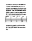
Aim: 'Build a sensor circuit to test the proximity of an object using a light detector to detect light from a bulb reflected from an object.' In this experiment I am going to build a sensor circuit using an LDR, I will then calibrate the sensor and use my results to test and improve the sensor circuit. The LDR works by having a very high resistance when the light intensity is low, which does not allow current to flow through the potential divider circuit. When the light intensity increases significantly, the resistance reduces dramatically and current can flow through the circuit. The resistor within a circuit can be changed to make the circuit more sensitive. The first thing I had to do was to test two different sensors to see which one had better sensitivity. From my results I could see that the LDR had the biggest input to output difference, meaning it was more sensitive than the photodiode. Next, I had to test which resistance would have the maximum output to input difference and thus give the LDR maximum sensitivity, shown in table A: Resistance/k? V out/V - Light on V out/V - Light off Difference/V 470 7.94 6.39 .55 220 7.93 6.86 .07 00 7.91 6.11 .80 47 7.88 4.94 2.94 22 7.81 3.51 4.30 0 7.66 2.10 5.56 From my results in table A I concluded that the 10k ? setting gave the maximum sensitivity as it had the biggest output to input

GCSE Electronic Products Specification Design and manufacture a Skeeball counter game that will count / add up points depending on which column the ball passes through.
GCSE Electronic Products Specification Design and manufacture a Skeeball counter game that will count / add up points depending on which column the ball passes through. It will need to: -Have five LDR's part number 58-01-0134 costing £0.30 for 1+ or as a bulk of 25+ for £0.24 from the website www.rapidonline.com. The LDR's will be used in the input of the circuit in series with another resistor so it will detect any change in the light density, changed when the ball passes the LDR' light source, which is an LED -Have a five 100k variable resistors part number UF97F costing £0.31 for 1+ from www.maplin.co.uk. They will be used in series with the LDR's. The reason I'm using a variable resistor as I will need to set a precise resistance to detect the ball when it passes the LDR's. -Have ten 555's part number 82-0336 costing £0.13 for 10+ from www.rapidonline.com. They will be used as five monostable and five astable in the control of my circuit. -Have five 10k resistors part number 63-2344 costing £0.17 from www.rapidonline.com. They will be used in the control part of the circuit connected to the 555's monostable pin's 6 and 7. -Have five 100uf capacitor part number 11-3087 costing £0.05 for 1+ from www.rapidonline.com. They will be used in series with the 10k resistor that is connected to pin 6 and 7 of the monostable 555. -Have twenty nine 360 ohms

Getting On Line Without a Computer or Internet Access at Home
Getting On Line Without a Computer or Internet Access at Home Introduction In today's world, there are many resources that are available to parents on the internet. Parents can find out about child development, help for children with special needs, positive parenting, health coverage, and many other important issues about your children. Parents can also get information about jobs and job training, immigration, and government benefits. But what can parents do if you don't have a computer or internet access at home? There's an easy and free answer - your local public library! Internet Access at Public Libraries Ninety-five percent of public libraries offer free access to computers and the internet. Public library patrons use library computers to learn basic computer and Internet skills. There is no reason to worry or be embarrassed about things like cost or lack of knowledge about how to use the Internet. Use of library computers and internet services is FREE! Librarians can provide one-on-one training. This informal, personal assistance can help you learn basic computer and Internet skills while you are looking for information. Some libraries even provide formal Internet training classes or workshops on basic computer skills, word processing, or using different databases. If you read and speak only Spanish, you may be wondering whether or not it's worth
The aim of my project is to produce a working 'People Counter', which will display a count on a seven-segment display every time a person passes a light sensor and be able to reset the counts at the end of each match day.
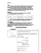
Aim: As Chairman of Sculthorpe United Football Club I like to keep up to date with daily income of the club, which mostly is from gate receipts. For our little club an easy method is required for counting the attendance each match day efficiently. The aim of my project is to produce a working 'People Counter', which will display a count on a seven-segment display every time a person passes a light sensor and be able to reset the counts at the end of each match day. Research: I have split my research into three distinct basic sections to be able to determine what components to use in the form of: Firstly I must consider the possible input blocks, which will provide a pulse from its output. There are two logical methods of approaching this problem. First method: The first solution would be a light sensor that will detect the break in light from the passing person thus generating a high pulse to be fed to the process components. From the 'Systems File - Electronics education magazine', I found three possible light sensor methods using a potential divider circuit which is seen in the following page. Input devices (Light Sensors) . LDR circuit: 2. Phototransistor: 3. Photo Diode: Second Method: The second possible solution other than the light sensor potential divider circuits would be to place a switch on the floor where passers will tread. The switch will close