
"Automatic model transformations using extended UML object diagrams in modeling environments".
SC207 Software Engineering - Term Paper 2003 Automatic Model Transformations Using Extended UML Object Diagrams in Modeling Environments Chathapuram V Satish Year 2 Computer Engineering Nanyang Technological University [email protected] TOPIC DETAILS "Automatic model transformations using extended UML object diagrams in modeling environments". Author: Dragan Milicev Source: Software Engineering, IEEE Transactions, Volume: 28, Issue: 4, Apr 2002, Page(s): 413-431 ABOUT THE AUTHOR Dragan Milicev received the diploma degree in 1993, Msc degree in 1995, and PhD degree in 2001 all in computer science at the School of Electrical Engineering at the University of Belgrade, Yugoslavia. His research interests include object oriented software engineering, metamodeling and information systems. His personal webpage can be found at http://www.rcub.bg.ac.yu/~dmilicev. INTRODUCTION Modeling is a critical part of all the activities that are involved in the deployment of an engineering system. Modeling tools that provide an interface to implement, apply, check and visualize the modeling process are available and make the entire process less cumbersome and tedious. One of the most important features of the modeling tools is the automatic generation of an output and this is the main focus of discussion in the above stated paper. The output can be documentation, source code, net

3SFE518 Computer System Organisation - Piping
Coursework for: Computer System Organisation 3SFE518 Malshani Nanayakkara 2007020 CONTENTS Introduction - About the Piping 3 Program Listing 4 Screenshots 7 ABOUT THE PIPING In order to be able to communicate between two terminals, pipes have been used. As pipes are FIFO structure (First In First Out), it is well suited to be used for such an application. Two pipes are created, one used to define a communication channel from the server terminal to the client and the other to define a communication channel from the client terminal to the server terminal. Lets call these two pipes, np1 and np2, where np1 is the connection from the client to the server. In the program running on the server terminal, the pipe np1 is opened in the read only mode. Thereby, allowing it to read the information being sent by the client terminal. In the program running on the client terminal, the pipe np2 is opened in the read only mode so the information being written by the server can be read by the client. Whenever the information from the pipe is being read, it is temporarily stored in a buffer before being printed out on the screen. PROGRAM LISTING fullduplex.h //Reference: http://developers.sun.com/solaris/articles/named_pipes.html #define NP1 "/tmp/np1" #define NP2 "/tmp/np2" #define MAX_BUF_SIZE 255 server.c //Reference :
Human Computer Interaction Project.
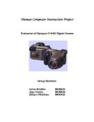
Human Computer Interaction Project Evaluation of Olympus C1400l Digital Camera Group Members: Lorna Brodbin 9838635 Jean Cronin 9838856 Gillian O'Sullivan 9840435 . Introduction "Every picture tells a story" An old saying that holds true. A picture can tell us more in an instant than a thousand words ever could. A picture records emotions, expressions, feelings and conveys them easily to the onlooker. Photographs capture hundreds of years of history be it on a world scale or at a personal level. We capture our weddings, births, birthdays and other occasions dear to us on camera because we want to hold on to that moment forever. Every time we look at a photograph we remember that day and relive that moment. The camera never lies. It takes a moment in time and freezes it. We rely on photographs as a tool to help us to understand and to remember the history of the world. Most of the worlds great historical events have been captured on film. A photograph of an innocent victim of war makes the victim real, like someone we knew rather than a name in a paper, and touches us far more deeply than stories in a book. Peoples descriptions of events are often tainted by exaggeration, imperfect memories and personal opinions but there is no denying the evidence of a photograph. The camera has come along way since the days of Niepcei. The first cameras were big and

Systems Development and Implementation
Systems Development and Implementation By Group C8: Amit Anand (PG040012) Gautam Waingankar (PG040055) Mithun Banerjee (PG040095) Sidharth Bhargava (PG040184) Suraj Jadhav (PG040205) Vineet Agrawal (PG040043) Systems Development and Implementation . Executive Summary 3 2. Sources of value for the user 3 3. The software value chain 4 3.1. Applications and infrastructure 4 3.2. Industry organization 5 4. Modularity in software development 6 4.1. Appropriation of value 7 4.1.1. Value for customers and end-users 8 4.1.2. Value for suppliers 8 4.1.3. Value for systems integrators 8 4.1.4. Pricing 8 4.1.5. Increasing vendor cooperation 9 4.1.6. Costs 9 5. Object oriented software development 10 6. Components based software development (CBSD) 11 7. The future of software development 11 7.1. Grid computing 11 7.2. Software as a utility 12 7.3. Pattern-centric development 12 7.4. Aspect oriented programming 12 8. Build, buy or rent? 13 8.1. Economic considerations 14 9. Implementation strategy - Big-bang or phased approach 14 9.1. Big Bang approach 15 9.2. Phased approach 15 0. References 17 . Executive Summary The report examines systems development and implementation with focus on the software value chain. It analyses the impact of marketplace issues on software design and the ways and means to create value for the customers. It takes a look at

3SFE504 - Object Oriented Programming - Linear and Independent Hash Table code
School of Informatics DEPARTMENT OF INFORMATION SYSTEMS AND COMPUTING 3SFE504: Object oriented programming COURSEWORK Student Id Student First Name Student Surname 2007053 Kavindya Isuru 2007020 Malshani Nanayakkara CONTENTS Page Introduction 3 Implementation Group Work 5 Student A Implementation 10 Assumption 24 Student B Implementation 25 Testing Student A: Test Plan 44 ScreenShots 45 Student B: Test Plan 50 ScreenShots 51 Self-Evaluation Individual Reports 59 INTRODUCTION This coursework was done in teams' of two group members. Group V was made of up of: N.T. I Kavindya and Malshani Nanayakkara In this project, we were asked to create a dictionary object, which was capable of storing words and its definitions. Each word could contain more than one definition. The dictionary object we created should contain the facilities of viewing the words in the dictionary, adding new words, searching new words and printing it to a file. The words and their definitions would be stored in an external file called 'defs.dat'. So every time, our application is run, the words and their definitions should be read in. We each created a hash table to accommodate these. Student A's part, done by Kavindya, reads in the word and stores them using the linear rehashing technique. Student B's part, done by Malshani, stores the words in the hash table using

This report is to describe the process I went through to create a 3D model of a chosen object and to animate it using 3D Studio Max software.
Contents 2. Introduction and Original Ideas. 4. Chosen idea. 5. First steps of creation. 7. Adding more objects 9. More detail through materials. 1. Lights, camera, animation. 2. Problems during creation. 3. Answers to questions. 5. References. Introduction This report is to describe the process I went through to create a 3D model of a chosen object and to animate it using 3D Studio Max software. During this report I will cover the following aspects: * The first ideas of which I came up with, and how I originally intended to create them using 3D Studio Max. * My chosen idea and how I began to set out my plan to create the object. * The steps I progressed through during creation. This will be the most detailed and significant part of the report. * Problems I had during creation and how those problems were tackled, also a few things I believe could be done better in the future. * Answers to questions provided by tutor as part of my assessment. Original Ideas To start with three ideas were very basically sketched and ideas of how they would be created were thought of. The three electrical objects which were short-listed were: Mobile phone: To create this it would take a simple couple of boxes representing different components of the phone (main unit, battery, sim card), the animation would show all these come together. Laptop computer: The Laptop would be

Rich Internet Applications
Multimedia Internet Development Year: 3 Rich Internet Applications To: James Williams From: Julian Moruzzi Table of Contents Page Section Description . Front Cover 2. Table of Contents 3. Table of Figures 4. .0 Introduction 5-8. 2.0 Concepts - RIA 9. 2.2 Current Stance in the technology 0. 2.3 Distributed RIA 1. 3.0 Design/ Implementation 3.1 Requirements 2. 4.0 Design 4.1 Colour Scheme 3. 4.2 Page Layout 4. 4.3 Template 4.4 Buttons 5,16 5.0 Implementation 5.1 Site Structure 7-19. 5.2 SWF Files 22. 6.0 Evaluation 23. 7.0 Test 24. 8.0 Bibliography 25-27. 9.0 Appendices Table of Figures Figure Page Description . 6. Adobe platform for RIAs 2. 8. where RIA lies 3. 1 Requirements Catalogue 4. 3. Design 5. 4. Website template 6. 6. Hierarchical chart of web pages 7. 7. Screen shots of SWF files 8. 20. xml for page buttons 9. 21. XML Class function- action script code .0 Introduction Originally the target of this report was to create a Rich Internet Application for an organisation which could be fictitious in nature. The application could be developed using one of the following ways: * Using Flash 8 & Action Script 2.0 programming to connect with some basic server side script, e.g. PHP. * Using Flash CS3 with Action script 3.0 to create a multimedia based application * Using Flex with

Test Thrice, Launch Once: Arian 5 disaster.
Test Thrice, Launch Once: Arian 5 disaster The Failure On June 4, 1996 an unmanned satellite-deploying rocket Ariane 5 was launched in Kourou at 1233 GMT. After about 40 seconds into the flight, the self-destruct of the space rocket was triggered. This was done in accordance with safety regulations due to the rupture of the links between the boosters and the main core stage of the rocket, caused by a dramatic change in direction that had taken place roughly 3 seconds earlier. The rocket was carrying four satellites that were going to be sent into orbit to monitor the sun. Ariane 5 was the result of a £5 billion launcher development by the ESA (European Space Agency), and the explosion itself destroyed the rocket and its payload, at a total cost of £500 million. The Cause of the Failure The origin of the failure was narrowed down to the Flight Control System, and more particularly, to the Inertial Reference System (SRI). To investigate the cause of the failure the European Space Agency (ESA) appointed an independent board. The following chain of events was established: * First 36 seconds of the flight were normal. * At H0+36.7 active SRI declared an operand error. The reason was a software exception, caused by the data conversion from a 64-bit floating-point number to 16-bit signed integer. That conversion can only be applied to a number less than 216, but was

Operations in a shuttle loom
Operations in a shuttle loom The first operation in a shuttle loom is called shedding. This is where a gap is created in the warp so that the weft can go straight in through the gap. A hield frame is used to shed the warp, which only contains one yarn. So what happens is all the odd number warps would rise above the even number warps so that weft insertion could take place. The gap between the odd and even warps is known as the shed. There are three frames for odd warps and three frames for even warps. The second operation is known as picking which is basically weft insertion. This is where the weft goes through the shed. A shuttle is used for picking which keeps going from one side to the other side of the fabric through the shed. The edge of the fabric is known as the selvedge, which is very strong, which is important so the fabric does not become frayed. There is a bristle inside of the shuttle, which stops the yarn becoming loose. This is important as if the yarn becomes loose it can lead to knots which would slow down the process. The area between the yarn and the fabric is known as cloth fell which is the point of fabric formation. Beat up is the process where the weft gets pushed into the cloth fell. To do this a reed is needed. There are three to four ends in each dent, which are the gaps in each reed. Then what basically happens is that the ends get beat up into

Evaluating Websites Usability - comparing 5 websites.
Higher Diploma in Software Development Web Development – Practical 2 Evaluating Websites Usability Website 1: www.lit.ie First Impressions: . URL is Good, Short, and very intuitive. 2. Download time is slow with image slideshow and animations loading at noticeably different times. 3. Home page seems cluttered with image slideshow on top, rolling text, links to videos. Text is readable and has a tool on the top tool bar for changing text size (Although this function only works on some text not all). Simple colours with red and blue being main colours used. 4. Only 40% of home page on one screen, scrolling up/down required. 5. Is obvious that it is home page to a college or learning institute with pictures of recent graduates, Links to college related links i.e. “Study @ Lit “ , “Current Students” etc clearly visible. 6. Moving mouse over key words on top tool bar gives drop down menus of links to all aspects of the Institute. 7. When hovering over the “About” keyword on the top tool bar, the pop down menu clearly details contact details, links to relevant information and presidents welcome note all increasing user confidence in site. Navigation: . Tool bar gives clear choices with drop down menu offering more detailed links 2. Site Map on bottom of webpage offers clear links to all relevant information. 3. Navigational links visible on the top tool