Internal resistance investigation - I will conduct the following investigation with the aim to find the internal resistance of a lemon battery, which I will construct myself.
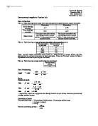
AS Physics - Internal resistance investigation I will conduct the following investigation with the aim to find the internal resistance of a lemon battery, which I will construct myself. The variables that could affect my experiment are as follows: * Size of lemon - I will conduct my experiment in no longer than an hour, allowing me to use the same lemon for all results * Size of metal electrodes - I will use the exact same electrodes throughout the whole experiment * Length of any connecting wires - I will use the exact same wires throughout my experiment and will not break the circuit once I have started collecting data * Resistance in the circuit - I will vary this using a highly sensitive variable resistor as shown in my method. To make my experiment fair I will only vary the most relevant variable to what I am investigating, which is the resistance in the circuit. All the other variables will be kept the same throughout the experiment as stated above. In my experiment I will need to measure the terminal pd, V, and the Current, I (in amps), for many values of resistance, R (in ?), I will measure these as I know that V=E-Ir so these are the values that I need to know if I am to eventually calculate the batteries internal resistance. I think that to make my graphs and conclusions accurate I will need to take at least 10 measurements, covering the full range of the
Measurement of capacitance by reed switch.
Physics Laboratory Report The number and the name of the experiment: Experiment 1- Measurement of capacitance by reed switch(TAS) The date of experiment:19 / 5 / 08 Objectives * Use a reed switch to measure the capacitance of capacitors. Apparatus Reed Switch Variable resistor Signal generator Micro ammeter Battery Box (with 4 cells of 1.5 V each) Voltmeter 2.2 Capacitor Connecting Leads Theory A reed switch is a two-way switch controlled by a signal generator as shown in Fig. C1. It can be used to charge and discharge a capacitor by connecting it across a power supply(point B) and a micro ammeter (point C) alternatively. When the reed switch connects the capacitor (C) to a power supply (V), the capacitor charges and stores electric charges. A few moments later, the reed switch connects the capacitor to a micro ammeter. The capacitor discharges in which the frequency () is the signal generator frequency. When the switch touches B, the capacitor is charged to a potential differences V, which is recorded by the voltmeter. The charge on the capacitor is : When the switch is in contact with C, the capacitor discharges through the micro ammeter. This process of charging and discharging occurs times per second. In each second, pulses of charge () flow through the micro ammeter. Hence, the current () through the micro ammeter is given by : Procedures . The

Resistivity of Lightbulbs
Lower 6th Quality of Measurement: 25 January 2009 Introduction: In this experiment I am aiming to investigate how different bulbs emit different light intensities depending on the potential difference applied to them. I will create my own sensor using a potential divider circuit using a Light Dependent Resistor (LDR) along with a lux-meter to calibrate it and then collect readings. What is a Potential Divider Circuit? Potential Dividers are part of many sensors. They consist of a voltage source along with some resistors in series. The potential of the voltage source[1], for example a power supply, is divided in proportion to the ratio of resistances. This means that you can choose the resistance to get the voltage you want across one of them. In the case of this experiment, the resistance across the LDR[2] varies with light intensity thus causing the potential difference across it to vary. The other resistor in series is a fixed resistor[3] which is there to compare the resistance of the LDR thus completing the ratio. The Voltmeter[4] records the potential difference across the fixed resistor thus giving the sensor a value. As the light levels increase, the resistance of the LDR falls and thus the potential difference across the LDR falls. In turn this increases the potential difference across the fixed resistor which is measured by the voltmeter. Increasing light levels
Find out whether or not changing the depth of the electrolyte affects the current.
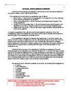
Aim: My aim is to find out whether or not changing the depth of the electrolyte affects the current. If so, is there a connection Method: I will set the experiment up as shown in the diagram. I will increase the depth of the electrolyte by 25ml each time. I will repeat the experiment 3 times to make sure I can spot any anomalous results. This way my results will be more accurate. Scientific Prediction: I predict that as I increase the depth of the electrolyte the current will be increased. By increasing the depth of the electrolyte it increases the surface area or the electrodes. By increasing the surface area the rate of reaction has increased, as there is a greater chance of a collision between the electrons and the electrodes. If I double the depth of the electrolyte, which is doubling the surface area, the current will double. Key Factors: Factors that will affect my experiment are depth, distance between electrolytes, voltage, and size of electrodes, concentration and temperature. My only variable will be the electrodes. I will keep the same all the others. I will attach the electrodes at a fixed distance on a splint this way they will not move so my results will be fair. I will be able to keep the voltage the same at 4V but not changing it on the power pack. I will use thwe same electrodes through the experiment, this way im not changing the size, but I will clean
A coursework on sensing temperature with voltage.
A coursework on sensing temperature with voltage. BY NNEKA EZEIGWE SENSING COURSEWORK. AIM: To devise a means of sensing temperature through a potential divider circuit with a thermistor. MATERIALS/APPARATUS NEEDED: Thermometer, Thermistor, Beaker, Electric kettle, Power supply, Multimeter, Resistance box. For the experiment to be successful a lot of things have to be considered and the first thing to consider when working with sensors is the properties of sensors. PROPERTIES OF A GOOD SENSOR High resolution: resolution refers to the smallest change a sensor can detect in the quantity it is measuring. This quality is highly related to precision. Sensitivity: This refers to the ratio of the change of output to the change of input. Sometimes however it is necessary to compromise on sensitivity so as to increase the range. However a good sensor should have reasonable sensitivity and range. Noise, random error and fluctuations: This is bound to occur as the input signal may fluctuate or the sensor itself may produce some noise. Small unsystematic variations occur in all experimental data. Taking an average however reduces the effect of this. Systematic error: Systematic error is very hard to detect and includes things like zero error, which are constant throughout the experiment. They do not really alter the results. Rather they tend to move the whole data and the
To prove ohms' law, and to study the relationship between current and potential difference (voltage).
2/3/2001 Ohm's Law Manaf Khatib Aim: To prove ohms' law, and to study the relationship between current and potential difference (voltage). Hypothesis: The current flowing through a metal wire is proportional to the potential difference across it (providing the temperature is constant). Apparatus: . Power Supply 2. Variable resistor 3. Ammeter 4. Voltmeter 5. Resistors 6. Electric wires Diagrams: R1: R2: R1 + R2 (in series): R1 + R2 (in parallel): Method: . Set up the apparatus 4 times as shown in the diagrams above 2. Set the power supply to 6v 3. Set the variable resistor to maximum resistance 4. Switch on the power and note the ammeter and voltmeter readings 5. Reduce the resistance of the variable resistor 6. Repeat steps 4, and 5 until at least five 8 sets of readings have been obtained 7. Change the setting of the apparatus as shown in the diagrams above, and perform steps 2 - 6 with each setting of apparatus Results: * Table of results for one resistor of 12? Current (A) Voltage (v) 0.18 2.18 0.20 2.30 0.22 2.52 0.24 2.79 0.26 3.02 0.28 3.39 0.30 3.62 0.38 4.41 *

resistivity if a nichrome wire
Aim: Throughout this experiment I aim to find out the resistivity of a nichrome wire. To do this I will measure the resistance of the nichrome wire at different lengths and from this I will be able to work out the resistance using the equation: Apparatus Apparatus Range Accuracy Purpose Quantity Nichrome wire N/A N/A This is the wire that I will be calculating the resistivity for. It's the subject of the investigation. Power pack 2V-12V ± 1 V The power pack is used, as it's a supply of the initial voltage. It also creates a potential difference in order for the flow of electrons to occur (current to flow). Crocodile clips n/a N/A I will be using these to hold them to the nichrome wire and to the voltmeter. I will use two to connect the wire to the voltmeter and the other end attached to 0m on the wire. The other two will be used to move along the different length on the wire, from 0.100m to 1.00m. 4 Micro screw Gauge 0-25mm ± 0.01mm This will help me measure the diameter of the nichrome wire. For this I can then be able to work out the cross sectional area of the wire by using the following equation: ?r2 Ruler stick 0m-1m ± 0.001m This is to measure the different length of the nichrome wire. Wires N/A N/A They are connectors in the circuit. They connect the wire to the power supply, the ammeter and to the voltmeter. 4 Ammeter 0-10
Investigate the effect of changing the length of a wire on the current flowing through it.
GCSE PHYSICS COURSEWORK: MODULE 5 ENERGY & ELECTRICITY Investigate the effect of changing the length of a wire on the current flowing through it. Skill Area P: Planning This coursework assignment deals with the relationship between the length of a wire and the current flowing through it. I will refer to other factors that determine current so that I can use scientific knowledge and understanding to turn ideas into an appropriate strategy. It is important to understand what current is to progress with the investigation. - Electricity is a flow of charged particles, which may be electrons or ions - Current is the measure of the rate of flow of electrical charge. Electric current is measured in amperes, A. The ampere is defined in terms of the magnetic effect of an electric current. - Electric charge is measured in coulombs, C. One coulomb is defined as the amount of charge passing a point in a circuit each second when the current is one ampere. - Current will only flow through a component if there is a voltage across that component. - The equation for current is defined as: I = V / R where I = current, V = voltage or potential difference or p.d., R = resistance. - Voltage is the "push" or energy given to the charges (usually electrons). - Ohm's Law states that the current through a metallic conductor at constant temperature is proportional to the voltage. -

The objective of this lab was to experiment with a negative feedback amplifier and predict its gain without the feedback.
20ECES465 Electronics Laboratory Section 001 1/04/03 Objective The objective of this lab was to experiment with a negative feedback amplifier and predict its gain without the feedback. Procedure After connecting the circuit per specifications in part one of the lab manual and verifying 7the voltage input and output we manipulated RFEEDBACK2 in order to achieve a gain of 100 v/v at a frequency of 1 KHz. We then made a screen dump of the Acircuit value. Since we were experimenting in the real world we could not use the ideal values for the components. Table 1 shows the ideal values called for in the lab report and the actual resistance values measured by a multimeter. Table 1: Resistance values Ideal (?) Real (?) 2.28k 2.26k 78.7k 78.6k .85k .85k 8.77k 8.8k 2.28k 2.29k 78.7k 78.7k 8.77k 8.74k .75k .750k We then swept the voltage in order to find the fH frequency. We then solved Equation 1 to get the feedback factor H. After we isolated H we could then predict what the gain of the circuit would be without the feedback factor. We then opened the circuit, which resulted in the RFEEDBACK2 value of infinity. The resulting circuit gave us an output of 15.09 V with an input of .01 V. This gave us a gain of 1509 V/V. We then swept the frequency to determine fH without the feedback. Then we calculated the gain-bandwidth product with and without
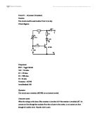
Circuit 31 – Dry sensor (Transistor).
Circuit 31 - Dry sensor (Transistor). Function This circuit could be used to detect if soil is too dry. Circuit diagram Components SW1 = Toggle Switch VR1 = 1M ohm R1 = 470 ohm R2 = 2200 ohm R3 =1k ohm Transistor = BC108 5mm Standard LED Operation This circuit uses a transistor (BC108) as an electronic switch. Transistor action. When the voltage on the base of the transistor is less than 0.6V the transistor is switched off. No current can flow through the transistor from the collector to the emitter, so no current can flow through R1 and the LED. Thus the LED is unlit. If more than 0.6V is applied to the base, the transistor switches on. Now current can pass easily from the collector to the emitter, so current can flow from the top rail, through R1, the LED and the transistor, back to the battery. The LED is now lit. Resistance of the probes Resistance of the probes will be referred to as RP. In dry conditions resistance RP will be extremely high, whereas in moist conditions resistance RP be relatively low. Consider the variable resistor (VR1) and RP in series. They form what is known as a voltage divider circuit. Operation of Voltage Divider Circuit Consider the value of the variable resistor set so its resistance is very high. Consider the probes in moist conditions, their resistance is very low. With the large resistance (VR1) and resistance RD