Current rating of fuses and MCB's.
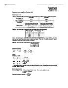
CURRENT RATING OF FUSES AND MCBS Name of Instructor: Miss. B.S.K. Subasinghe Name : Perera K.N.S. Index No : 020287 Field : ENTC Date of Per. : 10/12/2003 Date of Sub.: 19/12/2003 CALCULATIONS: For the fuse For MCB From graphs drawn, Fusing current for 5A fuse = Tripping current for 2A MCB = RESULTS Fusing Factor Tripping Factor DISCUSSION: Fuses and Miniature Circuit Breakers (MCBs) are used to protect electrical equipment and for the safety of the users. The conditions that require circuit protection are direct shorts, excessive current and excessive heat. When one or more of these conditions occur the above protective devices (connected in series with the supply) are able to disconnect the circuit thus preventing the danger. Fuses Circuit symbol: This provides protection by melting due to the heat produced because of ohmic resistance, when a higher than a rated current flows through it. There are three main types of fuses, Re-wirable fuses These have a thin wire that is held on a ceramic holder. The wire is designed to burn when a high current passes. An advantage is the reusability but it is vulnerable to mishandling where incorrect fusing elements can be fitted by inexperienced people, putting users in danger. Other Problems with this type are the oxidization (causes the cross section of the wire to reduce

investigating the relationship between the diameter and the current in a wire at its melting point
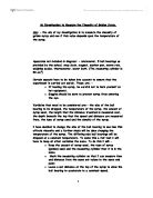
Investigation Report Aim Theory Electrical resistance is a measure of the degree to which an object opposes the passage of an electric current. The SI unit of electrical resistance is the ohm. Its reciprocal quantity is electrical conductance measured in siemens. Resistance is the property of any object or substance of resisting or opposing the flow of an electrical current. The quantity of resistance in an electric circuit determines the amount of current flowing in the circuit for any given voltage applied to the circuit. Some formulae for resistance are where R is the resistance of the object / ? V is the potential difference across the object / V I is the current passing through the object / A (Ref. http://en.wikipedia.org/wiki/Electrical_resistance) where R is the resistance/ ? ? is the resistivity / ?m l is the length of the wire / m A is the cross section area of the wire / m A = ?() = ? where A is area / m d is the diameter / m Putting the formulae together, so (Ref. http://physics.bu.edu/~duffy/PY106/Resistance.html) Aim of investigation The aim of this work is to investigate the relationship between the resistance and the diameter of the wire. Variables Variable Independent / Controlled / Dependent Resistance D Resistivity C Length of wire C Diameter I Prediction Since the theory suggests that So So the resistance should be
How the resistance of an ammeter changed when introduced into a circuit.
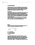
DC MEASUREMENTS The experiment was to find out how the resistance of both an ammeter and voltmeter, using both an ammeter and voltmeter changed when introduced into a circuit. From doing this it was found that the resistance of the ammeter decreases as both the emf and current decrease, however the avometer suggested that internal resistance increases with the voltage. Introduction Voltmeter's and ammeter's use a moving coil galvanometer to take the current and a mechanical pointer to display the current. When using analogue components an important factor to consider is full-scale deflection, which is when the maximum deflection of an analogue instrument such as a moving coil meter is reached. At present the full-scale deflection of most instruments is 10-50 ?A, but to overcome this shunting resistors are placed in parallel to carry the excess current. To take the voltage of an object, the shunting resistor must be placed in series, as the resistance of the moving-coil galvanometer is not very high. Some formulae which may be useful during this experiment is: Method The experiment firstly started by looking at calculating the resistance of the voltmeter. This was done by setting the circuit up as below: E = d.c. power supply M = Voltmeter being tested Rm = Voltmeter resistance I = Current The avometer was then placed upon successive ranges of 3v, 10v, 30v,
Investigation into the resistance of a filament lamp.
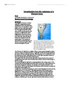
Investigation into the resistance of a filament lamp Aim To investigate Characteristics of a filament lamp Background Knowledge Filament bulb The tungsten filament in a modern light bulb is supported by several molybdenum wires. The ends of the support wires are imbedded in a glass button at the top of the glass support rod. The copper and nickel lead-in wires, which carry the current to the filament, are supported by a glass support stem. One lead-in wire is soldered to the metal contact at the base of the bulb, while the other is electrically connected to the side socket contact. The contacts are separated by an insulating plate. An electrical current can pass in either direction through the filament. The filament of a light bulb is a resistor. When a current passes through the resistor electrical energy is converted into heat. A light bulb converts current into power by the resistive element inside the light bulb. When the power level is sufficient to raise the temperature to above 1000 degrees Kelvin, visible light is produced, which can help us to estimate the temperature of the filament. The length of time that you leave the light bulb on determines the total amount of energy that has been used. The hot filament then radiates a fraction of this energy in the form of light. The current through the light bulb is not proportional to the voltage across it. This is
In this experiment we are investigating the effect of concentration on the current flowing through a copper sulpahte solution.
GCSE PHYSICS COURSEWORK In this experiment we are investigating the effect of concentration on the current flowing through a copper sulpahte solution. Prediction I think that the higher the concentration the higher the current passing through the solution, I also think that the higher the voltage, the higher the current. I think this will happen because there will be more copper sulphate molecules. Since there are more copper sulphate molecules, then there will be more sulphate ions giving up electrons to the anode (positive electrode) and more copper ions receiving electrons from the cathode, this means that there will be more electrons being transferred and so a higher current. The ions will break their ionic bonds because the copper plates are given a larger positive and negative charge by the battery (the circuit) and so the small force holding the ions together will be overpowered by the larger force of the electrodes on the ions. The liquid medium allows the ions to move freely and is what allows all of this to happen (The molecules in a liquid are more spaced out than in a solid (molecules in a solid bunched close together, with only enough room and energy to vibrate) and so this gives the ions the space and ability to move around and to actually get to the electrodes). To explain, ions are atoms that have gained or lost electrons to gain a charge. Copper gave up
To find the factors that affect the amount of E.M.F. being produced. The amount of E.M.F. produced during the experiment when each type of factors is change.
To find the factors that affect the amount of E.M.F. being produced. The amount of E.M.F. produced during the experiment when each type of factors is change. Planning Aim To find the factors that affect the amount of E.M.F. being produced. The amount of E.M.F. produced during the experiment when each type of factors is change. Background knowledge Electro-motive-force is the energy being supply to a charge. Battery is a type of energy. The energy that it provides is voltage. Battery voltage is sometime called electro-motive-force because it is used to "pump" around the electrons in the wire. The force can be generates by the moving of magnetic field as in the left-hand rules (field, current and force). It is the force that pushes the electrons around the circuit from the positive pole to the negative pole. That is why current directions in circuits are always marked from positive to negative. The voltage of the batteries varies in many volts e.g. 1.5V, 6V etc. A battery with a voltage of on volt is able to deliver one joule of energy for each coulomb of charge that passes through it. In other words, the voltage of a battery is the number of joules per coulomb that the battery can deliver when it is connected in a circuit. The law of left-hand rules or Fleming rules is that: * Thumb is for Motion. * First finger is for Field. * Second finger is for Current.
An Investigation into the Resistance of a Thermistor
An Investigation into the Resistance of a Thermistor Aim: Our aim is to investigate the temperature dependence of a thermistor, by heating it and measuring the current passing through it. We will collect three different pieces of data throughout the experiment, current, voltage and temperature. From this we will work out the resistance. Hypothesis: I predict that as we heat up the thermistor more current will pass through it. However the resistance of the circuit depends on the type of thermistor that we used (NTC or PTC). From looking ahead at the results our resistance decreased so this is a clear indication that we were using a Negative Temperature Coefficient thermal resistor and not a PTC, which would have increased resistance. So I predict that as heat enters the thermistor the electrons subsequently can move around and become free, the current will then increase as the electrons flow around the circuit and the resistance will decrease as more energy is supplied to it. The Voltage should not increase or decrease by more than 0.2V and I expect that the current will increase proportionally until the experiments end. Theory: My theory is that as we give energy the electrons can move around more and flow around the circuit. There is also a silicon semiconductor in the thermistor, which determines the amount of current to pass through the circuit. Method: Once you
To build and calibrate a sensor in order to calculate the temperature of surroundings.
Using a thermistor as a temperature sensor AIM: To build and calibrate a sensor in order to calculate the temperature of surroundings. METHOD Firstly I assembled all of the apparatus shown in the diagram. I then heated some water in a kettle, and poured it the big beaker. Next I lowered the beaker containing the ethanol into the hot water, with the thermistor just below the surface of the ethanol. I took the voltmeter reading for every 5 degrees Celsius as the temperature of the ethanol rose. I then added ice to cool the water down, again taking readings as the temperature of the ethanol declined. I repeated this experiment three times and took averages for each of the temperatures recorded. FAIR TESTING To ensure the test was entirely fair, I made sure that the same thermistor was used for each experiment. I also used the same volume of ethanol to ensure this had no effect on the result. The same thermometer was also used for the same reason. The potential difference delivered around the circuit was kept to a constant three volts, and I used the same fixed resistor to ensure that the potential difference split evenly across the resistor and thermistor, which would have severely affected my results. SAFETY ASPECTS The main safety aspect to consider whilst doing this experiment involved the use of ethanol in the experiment, especially as I planned to heat it. As ethanol

Resistor - What do resistors do?
Resistor What do resistors do? Resistors limit current. In a typical application, a resistor is connected in series with an LED: Enough current flows to make the LED light up, but not so much that the LED is damaged. Later in this Chapter, you will find out how to calculate a suitable value for this resistor. (LEDs are described in detail in Chapter 5.) The 'box' symbol for a fixed resistor is popular in the UK and Europe. A 'zig-zag' symbol is used in America and Japan: Resistors are used with transducers to make sensor subsystems. Transducers are electronic components which convert energy from one form into another, where one of the forms of energy is electrical. A light dependent resistor, or LDR, is an example of an input transducer. Changes in the brightness of the light shining onto the surface of the LDR result in changes in its resistance. As will be explained later, an input transducer is most often connected along with a resistor to to make a circuit called a potential divider. In this case, the output of the potential divider will be a voltage signal which reflects changes in illumination. Microphones and switches are input transducers. Output transducers include loudspeakers, filament lamps and LEDs. Can you think of other examples of transducers of each type? In other circuits, resistors are used to direct current flow to particular parts of the circuit, or
Test of the reed switch capacitors in series and in parallel
School: Class Number: Name: Class: Date: 1th May, 2008 Mark: Title Test of the reed switch - capacitors in series and in parallel Objective - To use a reed switch to measure the capacitance of some real capacitors, including those of series and parallel combinations - To investigate how the reed switch current varies with the frequency Apparatus Reed switch x1 Signal generator x1 Resistance substitution box x1 Battery box with 4 cells x1 Milliammeter x1 Voltmeter x1 Capacitors C1 and C2 Connecting wires Theory Reed switch current In the experiment, the reed switch allows the capacitor to be charged up and discharged rapidly. If a capacitor with capacitance C is charged up at a voltage V, the charge Q stored in it will be equal to CV. If the frequency f is operated by the reed switch, the charging up and discharging process will be repeated f times per second, the charge Q in the capacitor will be delivered to the milliammeter at the same rate. Assuming the capacitor is fully charged and discharged every time, the total charge Q total passing through the milliammeter per second is equal CVf, which is the theoretical current I. And the capacitance of the capacitor can be estimated by the formula C = I/ Vf. Capacitors in parallel If capacitors C1, C2, ..., CN are connected in parallel, the charges stored in each capacitor are shown as