What is an atomic orbital?
ATOMIC ORBITALS What is an atomic orbital? Orbitals and orbits When the a planet moves around the sun, you can plot a definite path for it which is called an orbit. A simple view of the atom looks similar and you may have pictured the electrons as orbiting around the nucleus. The truth is different, and electrons in fact inhabit regions of space known as orbitals. Orbits and orbitals sound similar, but they have quite different meanings. It is essential that you understand the difference between them. The impossibility of drawing orbits for electrons To plot a path for something you need to know exactly where the object is and be able to work out exactly where it's going to be an instant later. You can't do this for electrons. The Heisenberg Uncertainty Principle (not required at A'level) says - loosely - that you can't know with certainty both where an electron is and where it's going next. That makes it impossible to plot an orbit for an electron around a nucleus. Is this a big problem? No. If something is impossible, you have to accept it and find a way around it. Hydrogen's electron - the 1s orbital Suppose you had a single hydrogen atom and at a particular instant plotted the position of the one electron. Soon afterwards, you do the same thing, and find that it is in a new position. You have no idea how it got from the first place to the second. You keep on
Coursework To Find The Internal Resistance Of A PowerSupply
Coursework To Find The Internal Resistance Of A Power Supply The electrical supply on satellites needs to be kept at a constant voltage and the lost volts need to be taken into account when drawing different currents. Aim The aim of this investigation is to find the internal resistance of a power supply and to see if this value changes at five different voltage settings. Using a variable resistor to vary the load resistance at different voltage settings and obtaining both ampere and voltage readings and then plotting graphs of terminal potential difference against current to find the different values for the internal resistance of the power supply. Theory We can investigate the internal resistance of a power supply by setting up a circuit such as the one shown in figure 1. The voltmeter is connected in parallel to measure the potential difference across the power supply and the ammeter is connected in series to measure the flow of current. We would connect the voltmeter across the terminals of the power supply. The variable resistor is used to vary the load resistance to gain a series of values for current and corresponding voltmeter readings. Given that the power supply supports ohms law, potential difference is proportional to current under constant physical conditions. Due to this relationship, a graph of current (amps) against terminal potential difference (volts)

Find The Internal Resistance Of A Power Supply
Coursework To Find The Internal Resistance Of A Power Supply The electrical supply on satellites needs to be kept at a constant voltage and the lost volts need to be taken into account when drawing different currents. Aim The aim of this investigation is to find the internal resistance of a power supply and to see if this value changes at five different voltage settings. Using a variable resistor to vary the load resistance at different voltage settings and obtaining both ampere and voltage readings and then plotting graphs of terminal potential difference against current to find the different values for the internal resistance of the power supply. Theory We can investigate the internal resistance of a power supply by setting up a circuit such as the one shown in figure 1. The voltmeter is connected in parallel to measure the potential difference across the power supply and the ammeter is connected in series to measure the flow of current. We would connect the voltmeter across the terminals of the power supply. The variable resistor is used to vary the load resistance to gain a series of values for current and corresponding voltmeter readings. Given that the power supply supports ohms law, potential difference is proportional to current under constant physical conditions. Due to this relationship, a graph of current (amps) against terminal potential difference (volts)

Use of technology in a hospital radiology department. The department of imaging is one of the best equipped in the UK and provides a very full range of diagnostic and interventional services which include: X ray, Computer Tomography(CT), Magnetic Resonanc
IVA LEARNER INSTRUCTIONS TASK 1 A University College London Hospital (UCLH) is a teaching hospital in London, part of the University College London Hospital NHS Foundation Trust. It was founded in 1834, eight years after UCL (then known as the University College London as the North London Hospital in order to provide clinical training for the medical doctors. UCLH was officially opened in October 2005. It is the biggest and most ambitious hospital building project in the history of the NHS. UCLH provides many services. This includes: Accident and Emergency, clinic for cardiology outpatients, cancer care, critical care, endocrinology, general surgery, Ophthalmology, Dermatology, General medicine, Gynaecology, Rheumatology, Orthopaedics, Paediatrics and Urology. [ 1] This project mainly focuses on what they offer in the radiology department. The department of imaging is one of the best equipped in the UK and provides a very full range of diagnostic and interventional services which include: X ray, Computer Tomography(CT), Magnetic Resonance Imaging(MRI),Ultrasound (US), Intervention radiology, Fluoroscopy and plain film X ray. UCLH provides a comprehensive clinical service, offering a full range of procedures to both the trust and other hospitals throughout the UK. 12,000 patient studies are performed per year, using the UK's first Positron Emission Tomography (PET),
My experiments focus is to obtain an accurate measurement for a specific lenss power.
Quality of Measurement Coursework: 'The power of a lens' Andrew Ensten Aim My experiments' focus is to obtain an accurate measurement for a specific lens's power. This will be achieved by focusing on the lens equation: /v (curvature of wavefront after lens) = 1/u (curvature of wavefront before lens) + 1/f (power of the lens/curvature added by lens). By performing an experiment with a source of light, a lens, and a screen, I will obtain several 1/u and 1/v values. When these values are plotted on a 1/v against 1/u graph, they will hopefully give me an accurate estimation of the power of the lens by looking at the axes intercepts. Equipment: * Power pack: For each experiment I kept the output setting to 9 Volts to control the power being delivered to the filament lamp (as power = current x voltage). Power is proportional to intensity and so a brighter/darker output could result in a different range where the created image is in focus. * 2x Wires: These took the electric current from the power pack to the light source I was using. * Filament lamp: I chose a filament lamp over other sources of light as it is easy to tell when its' image is formed. This is because the filament is a very definable object. I used it for my first, third and fourth experiments. With a constant voltage output; the intensity of light was relatively constant. * Light Emitting Diode: I

Investigating the forces acting on a trolley on a ramp
Physics coursework Investigating the forces acting on a trolley on a ramp Contents Page 3 -> Method Page 4 -> Theory Page 7 -> Results Page 9 -> Error Page 18 -> Appendixes Method The aim of the investigation was to investigate the forces acting on a trolley as it rolled down a ramp, and also to investigate the factors which may contribute to the results. To do this, a trolley and a ramp set at a variety of angles of incline were used, and then, using a light gate, the speed at which the trolley was moving when it passed through the light gate was calculated. The variables were the starting distance of the trolley in relation to the light gate and the angle of the ramp. Firstly, the equipment was set up as in fig. 1. The trolley was then run down the ramp with a piece of card attached to the side. This card was of a known length and could hence be used to calculate the velocity at which the trolley was moving. While the light gate did actually calculate the velocity, it only gave the answer to 2 decimal places, whereas it gave the time to 2 decimal places. Furthermore, the light gate calculated the velocity with the assumption that the card was exactly 100mm, whereas when the card was actually measured, this was a value closer to 102mm (±0.5mm). Next, after the trolley had passed through the light gate, the information from that 'run' appeared

physics sensor coursework
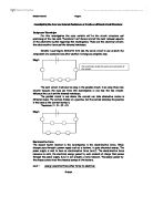
Physics coursework - sensor circuits In this investigation, I will be constructing a circuit which involves a sensor. I will calibrate this circuit and then test it in an environment outside the laboratory. The sensor I have chosen to use is a light dependant resistor, LDR. From my preliminary research, I found that this sensor works by changing its resistance as light levels are modified. This change is not proportional though, but a curve as shown: The resistance changes because the LDR is made up of a semi conducting material. When more photons hit the LDR, more electrons break free to act as charge carriers, thus reducing resistance in material. Circuit I shall incorporate the LDR into a potential divider circuit, in an arrangement called a "Wheatstone Bridge". An advantage of the Wheatstone Bridge, which is described in the "AS Advancing Physics" textbook, is that it only detects changes in the ratio of the two pairs of resistors. This means that an amplifier would only increase the changes in voltage output, rather than the whole thing. Also, the circuit would be unaffected by any outside changes - such as temperature - as the variable would cause the same proportional effect to each resistor. This means the ratio of each pair of resistors remains constant, so same output voltage. Above is the preliminary design of my circuit. Terminal A is connected to the
A2 OCR B Advancing Physics Coursework - Research and Report - The development of a Theory of Gravity
The development of a Theory of Gravity. What's behind it and where does it stand in relation to the other forces? Abstract: The Theory of Gravity has been transformed through the last century, from an original and important classical framework to more recent relativistic and then quantum interpretations, eventually culminating in a specific requirement to link it all together with the other forces and create a unified theory of everything. The search for unification is currently very much dependent upon experimentation and raises questions as to the scientific validity of String Theory and whether it exists as science or philosophy - or indeed just an elegant, but meaningless, example of mathematical aesthetics. . Introduction The ultimate goal for physicists is to devise a unified theory, which describes the universe all in one go. However, this proves difficult - there are partial theories which do not fit together, each predicting a limiting number of observations and neglecting others. Nevertheless the Standard Model exists as a framework for the coming together of partial theories. .1 The Basics of the Standard Model In matter there appears to be four basic forces at work. Gravity is the weakest of the four but acts over great distances, binding stars and galaxies together. The electromagnetic force is stronger and is responsible for holding atoms and molecules
Investigating the E.m.f and Internal Resistance of 2 cells on different circuit Structures.
Investigating the E.m.f and Internal Resistance of 2 cells on different circuit Structures Background Knowledge: For this investigation the main variable will be the circuit structure and positioning of the two cells. Therefore I will discuss in brief the most relevant aspects of the electricity module regarding this investigation. These are the electrical circuits, the electromotive force and the internal resistance. Circuits: According to Kirchoff's first law, the series circuit is one in which the components are connected one after another, forming one complete loop. Diag1: The next circuit I will also be using is the parallel circuit. I am using these two circuits because the main aim from this investigation is see how the two circuits influence the e.m.f and the internal resistance. The parallel circuit is one where the current can take alternative routes in different loops. The current divides at a junction, but the current entering the junction is the same as the current leaving it. Therefore: I = I1 + I2 + I3 Diag1: Electromotive force The second factor involved in the investigation is the electromotive force. When charges pass through a power supply such as a battery, it gains electrical energy. The power supply is said to have an electromotive force (e.m.f). The electromotive force measures in volts, the electrical energy gained by each coulomb of charge
What are Quantum Computers?
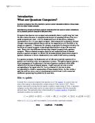
Introduction What are Quantum Computers? Quantum computers have the potential to perform certain calculations billions of times faster than any silicon-based computer. Scientists have already built basic quantum computers that can perform certain calculations; but a practical quantum computer is still years away. Computers have become more compact and considerably faster in performing their task, the task remains the same: to manipulate and interpret an encoding of binary bits into a useful computational result. A bit is a fundamental unit of information, classically represented as a 0 or 1 in your digital computer. Each classical bit is physically realized through a macroscopic physical system, such as the magnetization on a hard disk or the charge on a capacitor. A document, for example, comprised of n-characters stored on the hard drive of a typical computer is accordingly described by a string of 8n zeros and ones. Herein lies a key difference between your classical computer and a quantum computer. Where a classical computer obeys the well understood laws of classical physics, a quantum computer is a device that harnesses physical phenomenon unique to quantum mechanics to realize a fundamentally new mode of information processing. In a quantum computer, the fundamental unit of information (called a quantum bit or qubit), is not binary but rather more quaternary