Investigation into the resistance of a filament lamp.
Investigation into the resistance of a filament lamp Aim To investigate Characteristics of a filament lamp Background Knowledge Filament bulb The tungsten filament in a modern light bulb is supported by several molybdenum wires. The ends of the support wires are imbedded in a glass button at the top of the glass support rod. The copper and nickel lead-in wires, which carry the current to the filament, are supported by a glass support stem. One lead-in wire is soldered to the metal contact at the base of the bulb, while the other is electrically connected to the side socket contact. The contacts are separated by an insulating plate. An electrical current can pass in either direction through the filament. The filament of a light bulb is a resistor. When a current passes through the resistor electrical energy is converted into heat. A light bulb converts current into power by the resistive element inside the light bulb. When the power level is sufficient to raise the temperature to above 1000 degrees Kelvin, visible light is produced, which can help us to estimate the temperature of the filament. The length of time that you leave the light bulb on determines the total amount of energy that has been used. The hot filament then radiates a fraction of this energy in the form of light. The current through the light bulb is not proportional to the voltage across it. This is
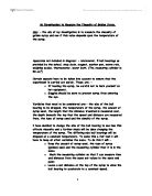
I am going to investigate what the resistivity is of a pencil lead. Pencil lead is made from a combination of finely ground graphite and clay, mixed with water and pressed together at high temperatures into thin rods
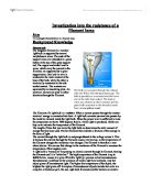
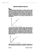
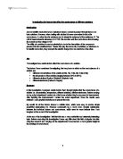
Finding Out The Resistivity Of Pencil Lead Plan Hypothesis I am going to investigate what the resistivity is of a pencil lead. Pencil lead is made from a combination of finely ground graphite and clay, mixed with water and pressed together at high temperatures into thin rods. Graphite is largely made up of carbon, which is quite a good conductor of electricity, but clay is not. This means the more clay that is mixed within the pencil lead the higher the resistance will be. The resistivity of a material is an individual property. It does not depend on the dimensions of the component only the materials from which it is made. To do this I will first have to find the resistance of the pencil lead. For the resistance I expect the graph to look something like this: The reason I predict the graph to look like this is because I think, and assume, that pencil lead will be an ohmic resistor. The graph will therefore look like this because the characteristic of an ohmic graph is that of above (a straight line). This means that current is directly proportional to the voltage. The gradient of the graph is also the resistance of the pencil lead. The gradient will then be taken along with the cross-sectional area and the length of the pencil lead and put into the resistivity formula. However I think that there is a distinct possibility that the pencil lead may have the

What Affects the Strength of Magnetism Exerted By an Electromagnet?
What Affects the Strength of Magnetism Exerted By an Electromagnet? Aim I am going to investigate what factors affect the strength of magnetic field exerted by an electromagnet. I will use a number of theories to plan my investigation. Iron, Cobalt or Nickel become magnetic when their domains point in the same direction. This is because all the N-poles add up at one end and the S-poles add up at the other end. These N-poles and S-poles then form concentrated magnetic areas relative to their direction. The will point towards 'Magnetic North'. This is the similar to what happens with lines of force. When any of the three magnetic metals become magnetic, they exert magnetic lines of force. These lines of force are called 'Magnetic Fields'. These lines of force exeunt from the 'North Pole' and are attracted to the 'South Pole', or any other metal with magnetic capabilities. We can demonstrate the 'lines of flux' (lines of force) by using a compass. A compass will follow the lines of flux from the North Pole. This is possible because the compass needle is magnetic with a North Pole and a South Pole. The North Pole of the needle is attracted along these lines of flux to the South Pole. This also demonstrates that 'Unlike Poles Attract'. Like Poles (e.g. North and North) repel each other. This can be established by bringing two North Poles together. This can be
How does changing the distance from a light source affect the power output of Photovoltaic Cells?
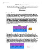
AS Physics Coursework assignment How does changing the distance from a light source affect the power output of Photovoltaic Cells? By Scott Humm How photovoltaic cells work The energy a photovoltaic cell uses comes from the sun. In the sun hydrogen nuclei fuse with each other and form helium nuclei and energy. It takes four hydrogen nuclei to form one helium nucleus. Photons are the energy by-products of the nuclear reactions in the sun. I intend to simulate this effect of the sun on the panel by having a powerful bulb close to the panel I am using. Photovoltaic cells are made of semiconductors. Silicon is the most frequently used semiconductor. When light hits the cell, a certain amount of it is absorbed into the semiconductor material and this absorbed energy is transferred into semiconductor. The absorbed energy knocks off electrons and they have the ability to flow freely. Electric fields in the Photovoltaic cell force the freed electrons to flow in a certain direction, forming a current, which can be used externally as a power source in calculators etc. This current, together with the cell's voltage (which is a result of the built-in electric field or fields), defines the power that the solar cell can produce. Photovoltaic cells have a positive and a negative layer. The positive layer is made from boron and goes underneath the silicon layer. The process of adding
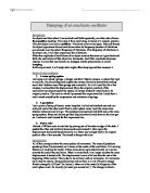
Damping of an mechanic oscillator.
Damping of an mechanic oscillator Introduction An object oscillates when it moves back and forth repeatedly, on either side of some fixed position (centre). If we stop it from oscillating, it returns to it original position. This sort object is called an oscillator. Vibrations exist in two types: free and forced. An object experiences forced oscillations when its frequency (number of vibrations per second) is not its natural frequency of vibrations. If its frequency of vibrations is its natural one, it will then experience free vibrations. When the amplitude of oscillations of an object remains the same as it goes back and forth, the oscillations of that object are harmonic. And if the amplitude decreases instead, it is said that oscillations are damped and the phenomenon is called damping. In this experiment, I will study what might affect damping and then measure it. Study of some oscillators . A mass-spring system I set using a tall stand, springs, a hanger and three 50gram masses, a system that I got to oscillate. I hold and displaced slightly the masses vertically downwards making sure I don't deform any of the springs and released it. As a let it oscillate for a few minutes, I noticed that the displacement (from the originial position) of the oscillations was deceasing for the system of masses tended to return back to its original position. The room in which I
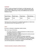
The Purpose of my sensing circuit is to regulate the temperature in a Steam Sauna which operates between the temperatures 30C - 60C
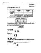
Introduction A Sauna is a small room designed to be heated to very high temperatures, with well-controlled humidity. Sauna’s are used for both recreational and therapeutic purposes. There are different types of Sauna, all with different heat sources and temperature ranges. Types Of Sauna Finnish Sauna Steam Sauna Infrared Sauna Temperature range (°C) 70-90 30-60 26-52 The Purpose of my sensing circuit is to regulate the temperature in a Steam Sauna which operates between the temperatures 30°C - 60°C Sensor My sensor is a thermistor (a temperature sensitive resistor). There are two types of thermistors. . PTC (Positive Temperature Co-efficient) thermistors for which an increase in temperature increases its resistance 2. NTC (Negative Temperature Co-efficient) thermistors for which an increase in temperature decreases its resistance Through my coursework I will be making use of a Negative temperature coefficient thermistor because I will be attempting to put a limit on the maximum temperature in the Sauna at which the steam generator can operate (also limiting the maximum temperature of the Sauna) by varying the potential difference across the steam generator as temperature changes. Principle of operation of a Negative Coefficient Thermistor Negative Temperature Coefficient thermistors are usually made from semiconductors (beads of metal oxides). They
Investigating a factor affecting the voltage output of a transformer.
GCSE Physics Coursework Plan Introduction I shall be investigating a factor affecting the voltage output of a transformer. In order to do this I shall be measuring the range of voltages that are induced across the secondary coil of the transformer when one factor is varied. To do this as accurately as possible and to obtain a fair test I shall ensure that every other variable factor in the practical remains constant. Background Theory Transformers are used industrially to increase the low voltages produced in electricity generation (25 kV) to higher voltages to be transported in the grid electricity supply's cables (250 kV), and then to decrease these voltages for use in domestic appliances (230 V). A transformer is a device for changing the voltage of alternating current (a.c.) signals and power supplies. Two coils are wound around an iron core, which is preferably laminated so as to reduce energy loss via eddy currents. Iron is a magnetically soft metal, which thus allows it to easily be magnetised and demagnetised (i.e. it doesn't retain a permanent magnetic field). Transformers utilise the effect of Electromagnetic Induction. The alternating voltage in the primary coil creates an alternating current, leading to an alternating magnetic field in the primary coil. The magnetic field lines move back and forth and are cut by the secondary coils, inducing a voltage in
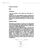
Investigating the factors that affect the conductance of a solution
Investigating the factors that affect the conductance of different solutions Introduction Just as metallic conductors have a resistance when a current is passed through them so do ionic solutions. However, when dealing with solution it is more convenient to look at its conductance, G, rather than its resistance and is simply the reciprocal of the resistance, R. The unit of measurement is siemens,?-1 G=1/R. We can also work the conductance from knowing the current and the voltage G=I/V. The ability of a solution to conduce electricity is due to the dissociation of the compounds presence into its constituent ions. Theses ions play the same role, in solutions, as electrons do in metallic conductors, they transport the electric charge from one electrode to the other. Aim To investigate how certain factors affect the conductance of a solution. The factors I have considered investigating, that may have an affect on the conductances of a solution are: * different concentrations of the solution (0.5M, 1M, 1.5M, 2M, 2.5M & 3M) * the temperature of the solution (ranging between 20?C to 90?C) * different solutions (Sodium Chloride& Sulphuric Acid) * different electrodes (Carbon & Copper) Summary In this investigation I analysed certain factors that I thought might affect the conductance of a solution i.e. concentration, temperature, different solutions, different electrodes.
Investigating Electromagnets
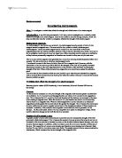
Physics coursework Investigating electromagnets Aim: To investigate a variable that affects the strength and effectiveness of an electromagnet. Introduction: In my following coursework, I will carry out an investigation on a variable, which affects the strength of an electromagnet. I tend to also create an accurate enough analysis, which will help me determine why the variable investigated, affected the strength of the electromagnet. Background research: An electromagnet is also known as a solenoid. An electromagnet usually consists of coils of wire wrapped around a magnetic core. The core could be Iron, nickel or cobalt, which are good electromagnets. Usually an electromagnet would consist of an iron core as this is the best at magnetising and proves readily available, because of these reasons I think the core, which I will use for the investigation would have to be an iron based core. Other cores that could be used prove ineffective as they become permanently magnetised so therefore are unuseful as they can only be used once. Above we can see the magnetic field generated by a round wire carrying electricity (picture taken from encarta). This shows the way in which an electromagnet works. If a solenoid is wound in the form of a helix, there will be a magnetic field. However, with the introduction of an iron core to go within the helix the strength of the field will be

Physics - Resistivity
PHYSICS AIM The aim of the experiment I am conducting is to find the resistivity of a 24 watt light bulb. This will be conducted through a series of experiments which will be followed by some calculations using formulas such as: Or ? is the resistivity (measured in ohm metres, ?-m) R is the electrical resistance of the material (measured in ohms,?) is the length of the piece of material (measured in metres, m) A is the cross-sectional area of the material (measured in square metres, m²). There are other equations that could be used to work out electrical resistivity, such as: E is the magnitude of the electric field (measured in volts per metre, V/m); J is the magnitude of the current density (measured in amperes per square metre, A/m²). Finally, electrical resistivity is also defined as the inverse of the conductivity ? (sigma), of the material, or: Electrical conductivity or is a measure of a material's ability to conduct an electric current. This is because resistivity and conductivity are reciprocals. I aim to use the first equation to work out resistivity by re-arranging it, like so: So if I can measure 'R', being resistance, 'A' being cross sectional area and 'l' being length of a light bulb, I can use the latter equation to work out the resistivity of the light bulb. RESISTIVITY The resistance of a wire depends on quite a few factors; these will