Technology, Culture & Communications, SEAS.
Introduction Michael E. Gorman Technology, Culture & Communications, SEAS University of Virginia To organize and depict, in abbreviated form, Alexander Graham Bell's invention of the telephone, we [1] have created a series of flowchart "maps" that include every sketch we have been able to locate from Bell's experimental notebooks, patents, depositions in court and correspondence. As the dates on the map indicate, time advances as on the maps from top to bottom. Multiple boxes spreading from right to left at the same time indicate that Bell was pursuing several lines of research at that point. When we say that Bell followed a path to the telephone, it makes his innovation process sound more linear and goal-directed than it really was, though Bell tried very hard to be scientific in his approach [2] and therefore was more linear than his competitors Edison and Gray. We refer to this flowchart as a map because the term flowchart implies more logical structure than does map, which may reflect the wanderings of an inventor. This series of maps is arranged hierarchically. The top level depicts the major experiments along Bell's path to a patent and to a device that successfully transmitted speech. When you click on one of the sketches in boxes on this top level, you will move to a lower-level map, depicting a series of experiments that were subsumed under that higher-level
Investigating how temperature affects the resistance in a wire
Aristide Mooyaart 11E Investigating how temperature affects the resistance in a wire Prediction / theory: All substances in the world are made up of protons, neutrons and electrons. All atoms have a nucleus in the centre that is made up of neutrons and protons, and a certain number of electrons circling around it; these electrons circling around the nucleus have a negative charge. These electrons orbit the nucleus in shells; they occupy different shells with the rules that: -The first shells (nearest to the nucleus are always occupied first -The maximum of electrons any shell can hold is 2n^2 (where n = the shell number) -The outer-most shell containing electrons can only hold a maximum of 8 electrons To demonstrate this here is a model of a metal atom (iron): All metals are known as n-type semiconductors as they all conduct electricity but all have resistance at room temperature. Metal atoms can bond together to form a giant structure, which is held together by metallic bonds; this means that there are many free electrons in these structures. This is because the metal atoms in the metallic structure have electrons on the outer-most shell that pass freely from one atom to another; these electrons can carry heat from one metal atom to another (making metals good conductors of heat). The electrons in these metal structures can be 'pushed' in one direction buy a lack of

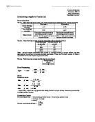
To find which of the circuits, shown below, are most suitable to measure a range of resistances, which the meters (the voltmeter and the ammeter) could be used to measure.
How do I connect this Voltmeter? Aim To find which of the circuits, shown below, are most suitable to measure a range of resistances, which the meters (the voltmeter and the ammeter) could be used to measure. Prediction I did not know which circuit would be the most accurate, to start with so I did a preliminary investigation, which consisted of setting up the two circuits above and then just putting two resistors in each and working out the required resistance. I did not see at the time that different value of resistance would make much of a difference until I commenced with my calculations. I discovered by using resistance values of 2200? and 4700?, that Circuit Two was better. Circuit One 2200? = 2105? by meter readings 4700? = 4364? by meter readings Circuit Two 2200? = 2222? by meter readings 4700? = 4600? by meter readings As you can see from these initial findings Circuit Two is the better circuit for measuring resistance values according to the labelled resistance. Hypothesis The manufacturers' specifications as given on the Voltmeter and Ammeter are as follows: Ammeter - Maximum Current 2mA, resistance 40? Voltmeter - Maximum Pd 5V, Maximum current 100µA After inspecting the above apparatus I have decided that the smallest value of the Current that I can accurately measure is 1 x 10⁻⁴ A and the maximum is 2 x 10⁻³ A. Any higher than 2 x
Investigating the factors affecting the size of current flowing through a length of resistivity putty.
04/02/97 ????? GCSE PHYSICS SC1 INVESTIGATION 996/7 INVESTIGATING THE FACTORS AFFECTING THE SIZE OF CURRENT FLOWING THROUGH A LENGTH OF RESISTIVITY PUTTY. CANDIDATE NUMBER 6247 CENTRE NUMBER 15131 PLANNING AIMS The main aim of this investigation will be to investigate the factors that have an effect on the size of the current passing through a length of resistivity putty. I will also try to explain my results using a number of models formulae and theories including Ohm's law, the formula for resistivity and a water model. VARIABLES Below is a list of the variables which are likely to have a major effect on the size of the current passing through a length of resistivity, putty: . The length of putty used. 2. The cross-sectional area of the putty. (Including the amount of contact between the plates and the putty). 3. The temperature of the putty. 4. The voltage across the putty. 5. The resistance of the wires etc. and the contact resistance between the plates and the putty. Other factors, for example the density of the carbon inside the putty, or the pressure at which the experiment is carried out, may also have an effect on the size of the current, however these factors would either be difficult to control in a school physics laboratory or are not likely to have a significant effect compared to the inaccuracies of the experiment. The two

Characteristics of Ohmic and Non Ohmic Conductors.
Physics Coursework Characteristics of Ohmic and Non Ohmic Conductors Every part of matter is made up of atoms. Atoms are called the building blocks of nature. These atoms consist of a nucleus and shells. The protons and neutrons are part of the nucleus and the electrons are distributed in shells around the nucleus. The protons have a positive charge, neutrons are not charged and the electrons are negatively charged. Electrons have no overall mass while neutrons and protons both have a mass of 1 unit. This is how the relative atomic mass is calculated, by adding up the number of protons and neutrons. The electrons are distributed in the shell in order of the amount of energy that they hold. So according to that I will introduce the concept of electricity. Electricity is a flow of electrons. Electricity can be transferred by some materials and some cannot transfer it. Conductors are any materials or substances that can allow heat or electricity to pass through them. Conduction means that heat or current is transferred from atom to atom on its way out. Some materials are good conductors; some are bad conductors while some do not conduct at all. Such materials or substances that do not allow heat or current to pass through are called insulators. These insulators usually do not have enough electrons to carry the current and thus they are non-conducting substances. One example
Coursework To Find The Internal Resistance Of A PowerSupply
Coursework To Find The Internal Resistance Of A Power Supply The electrical supply on satellites needs to be kept at a constant voltage and the lost volts need to be taken into account when drawing different currents. Aim The aim of this investigation is to find the internal resistance of a power supply and to see if this value changes at five different voltage settings. Using a variable resistor to vary the load resistance at different voltage settings and obtaining both ampere and voltage readings and then plotting graphs of terminal potential difference against current to find the different values for the internal resistance of the power supply. Theory We can investigate the internal resistance of a power supply by setting up a circuit such as the one shown in figure 1. The voltmeter is connected in parallel to measure the potential difference across the power supply and the ammeter is connected in series to measure the flow of current. We would connect the voltmeter across the terminals of the power supply. The variable resistor is used to vary the load resistance to gain a series of values for current and corresponding voltmeter readings. Given that the power supply supports ohms law, potential difference is proportional to current under constant physical conditions. Due to this relationship, a graph of current (amps) against terminal potential difference (volts)

Find The Internal Resistance Of A Power Supply
Coursework To Find The Internal Resistance Of A Power Supply The electrical supply on satellites needs to be kept at a constant voltage and the lost volts need to be taken into account when drawing different currents. Aim The aim of this investigation is to find the internal resistance of a power supply and to see if this value changes at five different voltage settings. Using a variable resistor to vary the load resistance at different voltage settings and obtaining both ampere and voltage readings and then plotting graphs of terminal potential difference against current to find the different values for the internal resistance of the power supply. Theory We can investigate the internal resistance of a power supply by setting up a circuit such as the one shown in figure 1. The voltmeter is connected in parallel to measure the potential difference across the power supply and the ammeter is connected in series to measure the flow of current. We would connect the voltmeter across the terminals of the power supply. The variable resistor is used to vary the load resistance to gain a series of values for current and corresponding voltmeter readings. Given that the power supply supports ohms law, potential difference is proportional to current under constant physical conditions. Due to this relationship, a graph of current (amps) against terminal potential difference (volts)

physics sensor coursework
Physics coursework - sensor circuits In this investigation, I will be constructing a circuit which involves a sensor. I will calibrate this circuit and then test it in an environment outside the laboratory. The sensor I have chosen to use is a light dependant resistor, LDR. From my preliminary research, I found that this sensor works by changing its resistance as light levels are modified. This change is not proportional though, but a curve as shown: The resistance changes because the LDR is made up of a semi conducting material. When more photons hit the LDR, more electrons break free to act as charge carriers, thus reducing resistance in material. Circuit I shall incorporate the LDR into a potential divider circuit, in an arrangement called a "Wheatstone Bridge". An advantage of the Wheatstone Bridge, which is described in the "AS Advancing Physics" textbook, is that it only detects changes in the ratio of the two pairs of resistors. This means that an amplifier would only increase the changes in voltage output, rather than the whole thing. Also, the circuit would be unaffected by any outside changes - such as temperature - as the variable would cause the same proportional effect to each resistor. This means the ratio of each pair of resistors remains constant, so same output voltage. Above is the preliminary design of my circuit. Terminal A is connected to the
Investigating the E.m.f and Internal Resistance of 2 cells on different circuit Structures.
Investigating the E.m.f and Internal Resistance of 2 cells on different circuit Structures Background Knowledge: For this investigation the main variable will be the circuit structure and positioning of the two cells. Therefore I will discuss in brief the most relevant aspects of the electricity module regarding this investigation. These are the electrical circuits, the electromotive force and the internal resistance. Circuits: According to Kirchoff's first law, the series circuit is one in which the components are connected one after another, forming one complete loop. Diag1: The next circuit I will also be using is the parallel circuit. I am using these two circuits because the main aim from this investigation is see how the two circuits influence the e.m.f and the internal resistance. The parallel circuit is one where the current can take alternative routes in different loops. The current divides at a junction, but the current entering the junction is the same as the current leaving it. Therefore: I = I1 + I2 + I3 Diag1: Electromotive force The second factor involved in the investigation is the electromotive force. When charges pass through a power supply such as a battery, it gains electrical energy. The power supply is said to have an electromotive force (e.m.f). The electromotive force measures in volts, the electrical energy gained by each coulomb of charge
Investigating the effect of 'length' on the resistance of a wire
NAME: Physics coursework Investigating the effect of length on the 7 ~PLAN~ For this investigation, I first decided to list all the factors which I think may affect the resistance of a wire and the reason for their importance. These factors are: * Material of the wire - If the wire is a conductor, more electric current will flow therefore the resistance would decrease, copper is an example of a good conductor. Insulators do not allow the flow of electric current which means the resistance will be at its peak. * The length of the wire - The longer the conductor, the further the electrons have to travel, the more likely they are to have collisions with metal ions and so the greater the resistance. * The temperature of the wire & surroundings - As the temperature increases the metal ions vibrate more (kinetic theory) leading to more frequent collisions with the electrons and therefore provide greater resistance to the flow of electrons. From the factors above, I chose the length of the wire to investigate. I obtained most of my information from: * "KEY SCIENCE for GCSE Physics" by Jim Breithaupt. * "Collins Total Revision GCSE Science" by Chris Sunley & Mike Smith. * "CGP GCSE Double Science Higher Physics" by Richard Parsons. * "Letts AS Physics" by Graham Booth. * Class work that I have done throughout my GCSE course. * The internet (educational websites,